CsPbI3 NC and fullerene hybrids
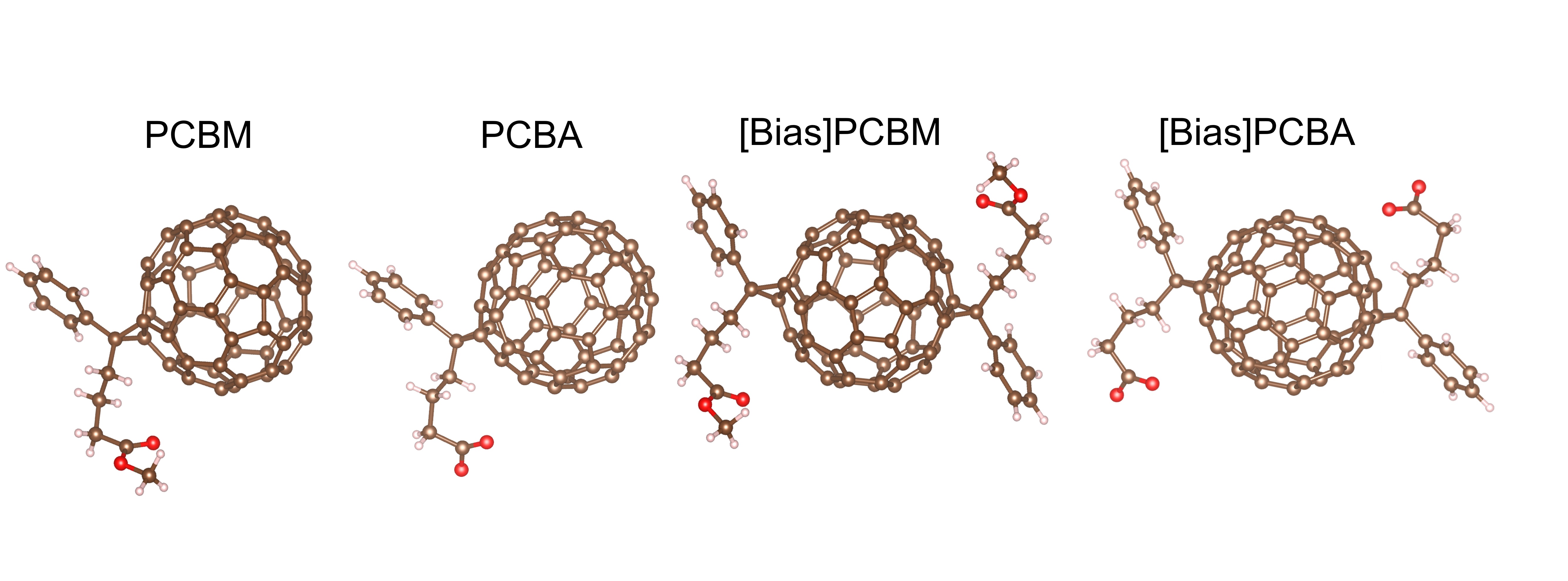
The prepared CsPbI3 NCs crystallized in the cubic phase (Figure S1), with an average diameter of 14.6 nm (Figure S2) and exhibited a photoluminescence quantum yield (PLQY) of ∼95%, suggesting high crystalline quality. To modulate the coupling between fullerene and CsPbI3 NC, we synthesized fullerene molecules with anchoring group (-COOH), i.e., PCBA and [Bias]PCBA, from the acid hydrolysis of PCBM and [Bias]PCBM respectively (Supplementary information methods). The molecular structures are shown in Scheme 1 and relevant nuclear magnetic resonance spectroscopy (NMR), optical absorption, and energy level are shown in Figure S3-5. The fullerene and CsPbI3 NC hybrid was obtained by mixing CsPbI3 NC with small quantity of fullerene, and then purified by successive precipitation and centrifugation cycles (see experiments details in supplementary information). XRD (Figure S2) and UV-vis absorption spectra (ABS, Figure S6) indicate no explicit detrimental effects of fullerene molecules on the chemical structure of CsPbI3 NCs and the absorption contribution from fullerene molecules is completely negligible in our experiments.
Pump dependent HC relaxion in CsPbI3 NCs.
Total HC quenching in CsPbI3 NCs consists of two parts: HC relaxion and HC capture. Quantifying HC capture requires removing the intrinsic relaxion contribution, which drives us to establish a more general image describing the pump power dependent HC relaxion in perovskite NC12, 22. Figure 1a-b show the pseudo colour TA maps of CsPbI3 NCs excited at 470 nm under a lower (16 µJ/cm2) and higher (200 µJ/cm2) pump fluence, corresponding to initial average generated exciton (e-h pair) numbers per NCs < N > ~ 0.2 and < N > ~ 2.3 respectively (see Figure S7). For both cases, immediately after photoexcitation, positive photo induced absorption (PIA) peak emerged below the bandgap with respect to bandgap remoralization (BGR) effect9, 22. Decay of PIA occurred once the HC cooled down to occupy the states near band edge, simultaneously, band filling induced negative photobleaching (PB) signal with high energy tail gradually settled in near the bandgap and finally replaced the PIA signal. In lower intensity pump, global analysis of TA spectrum (Figure S8, evolution-associated spectra (EAS)) indicates PIA displays a consistent dynamic with the broadened PB. The kinetical curve of this EAS component is shown in Fig. 1c (dashed black line). In previous research, PIA decay has been used to evaluate HC lifetime9. Here, the kinetic curve describing PIA signal was chosen at 1.76 eV, where the contribution of PB signal is negligible. Along with the thermalization and relaxion of HCs, the ground state bleaching (GSB) gradually increases and reaches the maximum, which can be fitted with a convolution of single-exponential growth function and instrument response function (IRF) of TA measurement to yield a rise time. In many works, the HC lifetime was also estimated by monitoring this rise time23, 24. When the HCs totally cool down to be excited carriers at band edge, the broadened PB with high-energy tail will compress to the shape close to secant hyperbolic function or Gaussian function broadened GSB of exciton (Figure S8). Note that the weak positive absorption band (PIA2) existed at the higher energy side of the isosbestic point (IBP at 1.96 eV in Figure S8) on GSB shows small deviation accounted for excited carrier absorption at band edge12. In the presence of HCs, isosbestic point will shift to higher energy, at the meantime, the signal at the energy corresponding to the isosbestic point of GSB becomes negative PB, which means any new PB feature observed at this point can be attributed to the HC signal. In view of this, we propose to use the transient kinetic at this IBP to image the bleaching signal of HC.
As shown in Fig. 1c, the GSB formation, PIA decay, IBP decay and EAS decay at lower pump, are kinetically correlated with a similar lifetime ~ 0.84 ps, which means these methods tend to acquire a same HC relaxion time. However, these kinetical curves are no longer completely synchronized at high-fluence pump (Fig. 1b,d). Obviously, the decay at IBP exhibits slower dynamic than the formation of GSB and the PIA decay but still keeps in consistent with the existence of high energy tail that reveals the energy distribution of HCs. Note that EAS misses in Fig. 1d since it cannot provide a clear picture to depict the dynamic relevant components under the influence of more outstanding band filling effect as shown in Figure S8. We ascribe the non-synchronous dynamics in these curves to the appearance of multi-particle effects including Auger recombination and concomitant Auger heating, in which Auger recombination losses cold carriers and displays as the intensity-dependent rapid shortening of the GSB dynamics (Figure S7), while Auger heating contributes to further retardation of HC relaxation and plays an important role in practical HC solar cells12, 22 .
Intrinsic energy losses of CsPbI3 NC in the processes of HC relaxion are further discussed via the analysis of time-dependent carrier temperature Tc (Fig. 1e). To ensure that all population of HCs reach quasi-equilibrium and occupy the states at near band edge forming Fermi-Dirac distribution, we analyzed the HC cooling dynamics after a 0.3 ~ 1 ps delay (depend on pump intensity). Average carrier temperature Tc can be extracted by fitting the high-energy band tail of GSB22, 24 according to 1/(1 + exp(E-Ef)/kBTc), where Ef is quasi-Fermi energy, kB is Boltzmann constant (Figure S9). The initial excess energy (∆Eexcess) of carriers stimulated with 2.64 eV (470 nm) pump energy (Epump) relative to band edge is expected to be 0.36 eV corresponds to a highest effective temperature Tc ~2700 K (e.g., ∆Eexcess=(Epump-Eg)/2-Eg and Tc~2∆E/3kB, assuming electron and hole in perovskites have similar the effective mass and hold similar temperature with each other10, 23, 25). The drop of the effective temperature of carriers from initial pump to quasi-equilibrium are ascribed to carrier-carrier scattering. Subsequent temperature losses are numerically fitted with three temperature model (TTM)26, 27, which provides a clear picture of various stages of HC relaxation by coupling Auger reheating into the rate equations of HCs and longitudinal optical (LO) phonons (supplementary Note 1). Under low pump fluence, the HC relaxion displays single exponential decay and takes around 0.76 ps (Fig. 1e), which is similar to the dynamics of GSB formation, PIA decay, IBP kinetic in Fig. 1c. The scattering interaction between carrier and longitudinal optical (LO) phonons contributes to the fast drop of HC temperature. Whereafter, the LO-phonons rapidly release obtained excess energy to lattice without bottleneck, see LO-phonon temperature (Tp, dash purple line in Fig. 1e). The energy power loss rate Jr (e.g.-1.5kBTc) in this regime can be fitted with LO-phonon interaction model (supplementary Note 2), the fitted LO–phonon decay time τLO (~ 0.51 ps) is consistent with previous reports28.
Under high pump fluence, HC relaxation changes significantly compared with that at low-fluence pump. Specifically, the HC cooling process is not terminated within picosecond but prolonged to tens of picoseconds. In this case, the time dependent temperature can be divided into three stages. Stage I is dominated by LO-phonon interaction as same as temperature decay under low pump fluence. It can be demonstrated from the similar value of τLO (0.47 ps) fitted from the energy power loss rate at this stage. The difference of stage I with the temperature decay under low pump fluence lies on HCs eventually heated the LO-phonon to a higher temperature, as the dash red line in Fig. 1e. After the LO-phonons attaching to peak temperature, the LO-phonons release energy to acoustic phonon or lattice with a slow rate probably due to hot phonon bottleneck effect. In addition, Auger reheating also contributes the slow HC relaxation in this stage, which can be found in the accelerated temperature decay after removing the Auger reheating effect (solid black line in Fig. 1e). We think stage III is mainly on account of Auger reheating effect since the behavior of energy power loss rate follows quadratic dependence28 on (Tc-TL) remarkably well (TL is lattice temperature) and phonon bottleneck can be neglected due to Tp is close to TL at this stage. In brief, phonon bottleneck and Auger reheating effects greatly prolong the HC cooling in our CsPbI3 NCs. Specially, when Tc cooled down to room temperature (~ 70 ps) the dynamic curve at IBP just decayed into zero, hence, the transient kinetic at IBP is demonstrated with more general applicability to quantify the HC relaxation for different conditions than GSB formation, PIA decay and EAS.
HC capture dynamics
HC capture from CsPbI3 NC to fullerene is explored based on above discussion. Figure 2a shows the HC capture schematic diagram in CsPbI3 NC-fullerene hybrids. Photo generated HCs quench by both intrinsic cooling of NCs and HC capture. If HC capture occurs, the total HC quenching will be accelerated and reflected in Tc and IBP kinetic. As result, we can calculate the capture rate and efficiency according to TA signal difference in CsPbI3 NC and CsPbI3 NC-fullerene hybrid, although the TA signals of fullerene molecule we introduced has beyond the response limit of our measurements (Figure S10). Figure 2b displays the time-dependent carrier temperature Tc of CsPbI3 NC and CsPbI3 NC-fullerene hybrids under same pump intensity (< N > ~ 2.3). Here, we note that the photon numbers per NC are thought to be identical due to the negligible absorption of fullerene. As expected, the forbidden hot carrier capture is observed in CsPbI3 NC-PCBM hybrid and CsPbI3 NC-[Bias]PCBM hybrid. Surprisingly, these results are fully reversed in our specially prepared CsPbI3 NC-PCBA hybrid and CsPbI3 NC-[Bias]PCBA hybrid proved by the obvious acceleration of Tc decrease processes (see more details about TA data in Figure S11-13). Since the temperature of HC has already shown apparent decrease around initial several picoseconds when cold carriers have not yet been captured in quantity, it is reasonable to rule out the influence of cold carrier quenching on state filling and attribute the decrease of Tc to the HC capture. The carrier capture induced electronic energy power loss rate (Je) as a function of carrier temperature was further calculated to remove the influence of intrinsic HC cooling by the subtraction between the intrinsic Jr and the Jr for CsPbI3 NC-fullerene hybrid, that is Je(FDs) = Jr(CsPbI3)-Jr(CsPbI3-fullerene). For PCBA and [Bias]PCBA, Je exhibits an apparent increasement starting from carrier temperature higher than 850K and increase steadily with Tc (Fig. 2c). Inset of Fig. 2c indicates that HC transfer from CsPbI3 NC boundary to PCBA and [Bias]PCBA exists a threshold energy (Tc > 850 K), which could be related to the location of energy level coupling (discuss latter). Figure 2d shows the transient kinetics at IBP for CsPbI3 NCs with and without fullerene (< N > ~ 2.3). In consistent with temperature results, it is apparent that introduction of PCBA or [Bias]PCBA accelerates the IBP decay (more IBP kinetics see Figure S14). By fitting the transient kinetics at IBP, the capture efficiency (η) of HCs (Fig. 2e) can be estimated according to η = 1-τfullrene/τNCs, where τfullerene and τNCs are the lifetime of CsPbI3 NC-fullerene hybrid and CsPbI3 NC respectively. The acquired η is significantly improved with increasing pump fluence. The results confirm that, the presence of bottleneck and Auger reheating under high pump fluence is great beneficial for the HC capture, because long HC lifetime caused by these effects can keep HC above the threshold energy for longer time. When competing with intrinsic HC relaxion, HCs have higher possibility to pass through the interface between NC and fullerene (see Fig. 2a). Besides, we also notice the small magnitude declines of η under < N > ~ 5. It is possibly ascribed to the saturation of carriers under high pump power dominated by Auger recombination. Finally, a maximum capture efficiency (up to 84%) is acquired under < N > ~ 2.3 by using [Bias]PCBA as selective materials. This result not only reverses the originally forbidden hot carrier capture in CsPbI3 NC-fullerene hybrid but also displays great performance for future application.
Binding and electronic coupling in CsPbI3 NC-fullerene hybrid
Notably, the functional design of fullerene molecules completely reversed the hot carrier capture process in CsPbI3 NC-fullerene hybrids. This was conceivably driven by the chemical binding and physical coupling between the modified fullerene molecules and CsPbI3 NCs. In Fig. 3a-c, fluorescence quenching technique was adopted here to reveal the their binding image hiding behind the following possible fluorescence quenching mechanisms29: (1) dynamic quenching, (2) static quenching (3) combined dynamic and static quenching (see detail illustration in supplementary Note 3). Importantly, this kind of spectrum analysis provides very high sensitivity even for the weak interactions thus being widely used in doner-acceptor system29, 30. The quenching data (Figure S15) is presented as a plot of F0/F versus Q, where F0 and F are the stable fluorescence intensities of NCs in the absence and presence of fullerene, respectively, Q is the concentration of fullerene. As expected, tuning fullerene structure triggers dramatical changes in their binding modes with CsPbI3 NCs. In the CsPbI3 NC-PCBM (or [Bias]PCBM) system (Fig. 3b), the downward curvature indicates the system undergoes dynamic quenching processes, in which NCs and fullerene bind with light driven collision31. This mechanism is also supported by the unchanged ABS (Figure S6) and solution colour (digital images in inset of Fig. 3b) compared with intrinsic CsPbI3 NCs. Quenching of this mode can be analyzed using equation F0/∆F = fa-1Ka-1[Q]-1+fa-1, where fa is the fraction of NCs with high surface accessibility to fullerene molecules and Ka is quenching constant of accessible NCs31. Based on the slope and intercept of the reframed plots in inset of Fig. 3, we determined the fa and Ka for CsPbI3 NC-PCBM and CsPbI3 NC-[Bias]PCBM respectively (see Table 1). The results indicate functional group of fullerene plays a critical role in their binding of CsPbI3 NCs; For [Bias]PCBM, 92% of NCs own high surface accessibility, while for PCBM only 48.9% of NCs own high surface accessibility. [Bias]PCBM displays more effective dynamic quenching than PCBM, which is probable due to double numbers of ester groups. The physical interaction processes between the accessible NCs and these fullerene molecules are clarified in the upper image of Fig. 3a. Due to their binding is realized transient physical collision, there is lack of condition for stable electronic coupling which is the important factors for hot carrier capture. Besides, the slow molecule diffusion process in their binding mode limits the carrier transfer rate in their hybrids, thus, carrier capture here is hardly to compete with HC cooling.
With regard to the quenching in CsPbI3 NC-PCBA and CsPbI3 NC-[Bias]PCBA, two stages are observed in their Stern-Volmer plots: one has positive curvature, another is linear plot (see Fig. 3c). Here, we exclude other possibilities and propose to use the formula combining the dynamic quenching model and modified static quenching (by forming complexes) model to depict our positive Stern-Volmer plots, that is F0/F=(KD[Q + 1])(KB[Q]n+1), where KD is dynamic quenching constant, KB is the binding constant of the static complex, n is the number of equivalent binding sites for PCBA/[Bias]PCBA onto per CsPbI3 NC. The derivation details and more discussion is shown in supplementary information Note 4. From the fitting results in Table 1, KB is almost six orders of magnitude larger than KD indicating that the quenching by forming static complex holds the dominant position in the first quenching stage. The value n ~ 2 means about two fullerene molecules on average are bonding with per CsPbI3 NC. The formation of static complex provides very high bonding stability and close contact distance, which facilitate the efficient coupling of electronic state for fast carrier transfer. The downer image of Fig. 3a visualizes these interaction processes. For CsPbI3 NC-PCBA/[Bias]PCBA hybrid, the core point lies on the formation of stable complexes that can be further demonstrated by the black dispersions under room light (digital images in inset of Fig. 3c). X-ray photoelectron spectrum (XPS) and attenuated total reflection mode of Fourier transform infrared spectra (ATR-FTIR) illustrate that PCBA and [Bias]PCBA would prefer chemically anchoring onto the uncapped atoms rather than extensively replacing the long chain ligand by traditional ligand exchange (See supplementary Figure S16-17 and Note 5), in agreement with the small number of equivalent binding sites. In addition, the linear stage in the plots indicates only one standard type of quenching occurs. Due to the binding sites have already been occupied, the specific interaction by forming static complex for excessive PCBA/[Bias]PCBA is nearly saturated within this stage. As result, it is easily attributing the quenching to standard dynamic quenching rather than standard static quenching although both display linear plots. The equation describing this situation is F0/F = KD2Q+b, where KD2 is dynamic quenching constant, b is constant29. The consistent orders of magnitude of KD2 and Ka (see Table 1, PCBM vs PCBA, [Bias]PCBM vs [Bias] PCBA) also support the fact of dynamic quenching in this stage. This result illustrates that it is very low yields for enhancing the carrier capture by excessively introducing PCBA or [Bias] PCBA. Along with quenching stages, shift of photoluminescence peak also displayed consistent laws. Detail discussions are shown in supplementary Note 6. Collectively, by fluorescence quenching technique, we find our synthesized PCBA and [Bias]PCBA completely changes their (PCBM [Bias]PCBM) original binding modes with NCs. The stable chemical binding is the precondition for electronic wavefunction coupling in CsPbI3-fulleren hybrid.
Table 1
Parameters fitted from Stern − Volmer plots
| |
Ka (M-1)
|
fa
|
KD (M-1)
|
n
|
Kb (M-n)
|
KD2 (M-1)
|
|
PCBM
|
5.71×10⁷
|
48.9%
|
|
|
|
|
|
[Bias]PCBM
|
1.46×10⁸
|
92.0%
|
|
|
|
|
|
PCBA
|
|
|
2.47×10⁶
|
2.06
|
2.09×10¹²
|
8.52×10⁷
|
|
[Bias]PCBA
|
|
|
1.21×10⁷
|
2.12
|
1.84×10¹³
|
2.22×10⁸
|
Figure 3d shows the second derivative absorption spectra that eliminate the linear background function and further resolve the fine structure of electronic states. In quantum confinement systems, the minimal value points at second derivative ABS are thought to be related with the electronic state energy levels32, 33. Here, the weak absorption of fullerene in the CsPbI3 NC-fullerene hybrid dispersions has been removed before calculating derivative ABS. Thus, the changes are only associated with the effective coupling between fullerene and CsPbI3 NCs. From the location of the significant differences in ABS, it can be easily conjectured that both PCBA and [Bias]PCBA have significant influences on the electronic states of CsPbI3 NCs at both band edge and high energy level while PCBM and [Bias]PCBM have not. For CsPbI3-PCBA/[Bias]PCBA NCs, the energy difference between the minimal value points at high energy level (2.12 eV) and band edge (1.90 eV) is ~ 0.22 eV i.e., 825 K, in consistent with the HC transfer threshold, implying that the coupling electronic states provide channels for HC transfer from CsPbI3 NCs to PCBA/[Bias]PCBA molecules. Besides, excitation power dependent PL spectrum (supplementary Figure S18) indicated the changes at band edge are attributed to electric-field induced exciton delocalization. This is also supported by the decrease of exciton binding energy (from 25 meV to 7 meV, clarified in supplementary Figure S19-20, Note 7 and Table S1) and highly efficient (~ 100%) cold electron transfer (Figure S21). The electric field induced exciton delocalization driven by FDs has also been reported in bulk perovskite film34 and the theoretical calculations relying on the conception of the overall ligand/core adduct as an indecomposable species also demonstrated the mixing orbitals would lead to delocalized states throughout the whole band structure while NC and ligand experience each other’s electric field35, 36. Thus, we infer that the electric-field tuned HC transfer may also occur in our experiments.
DFT calculation
Density of function theory (DFT) was applied to further understand the nature of the HC capture. Figure 4a shows the binding mode of OA, PCBA and PCBM with the optimized surface structures with CsI-termination and PbI2-termination, respectively. More details of structural models and computational settings can be found in Supplementary Information and in Figure S22-23. Similar with OA, PCBA binds to both CsI- and PbI2-terminated slabs via covalent bonds. On PbI2-terminated NC, both Pb-O bond lengths (LPb-O(1) ≈ 2.51 Å and LPb-O(2) ≈ 2.43 Å) are smaller than the sum of Pb2+ (1.2 Å) and O2− (1.4 Å) ion radii, illustrating that the effective bonding is realized by bidentate chelating between the two O atoms of PCBA and Pb atoms. Unlike PbI2-termination, the bonding in CsI-termination is realized with the bidentate bridging mode, which have two O atoms bond with Pb atom and Cs atom separately. Whether the bonding mode is bidentate bridging or chelating, such bonding through multiple atoms has been shown to give extra stability to the complex than monodentate37. The binding energy (in Fig. 4b) between PCBA and CsPbI3 NC is large in negative values (about − 4 eV) regardless of surface termination, illustrating PCBA can spontaneously anchor onto NC surface. In addition, slightly lower binding energy compared to OA (about − 4.4 eV) suggests the slight preference of OA compared to PCBA, in agreement with experiments from Stern-Volmer analysis, XPS and FTIR. In contract, the small binding energy (almost zero) between PCBM and CsPbI3 NCs demonstrates the weak interaction. As shown in the charge density difference (CDD)(Figure S24), PCBM has no notable charge redistribution at the interface, indicating the PCBM molecular is physically adsorbed on the perovskite surface, which is different from the chemical bonding between PCBA and CsPbI3 surface. From the partial density of state (pDOS) of the above-mentioned bonding atoms (Fig. 4c-d), we see that large area of the synergic electronic state peak of bonding Pb atom with the electronic state of O atoms indicating their strong coupling. This electronic coupling helps the electronic wavefunction in NC extends in space to PCBA and works as the bridge for HC capture. Besides, the overlap of the DOS between the whole PCBA with CsPbI3 is another necessary condition for HC capture (Figure S25). Taking OA as an example, despite the coupling at interface bonding (Figure S26), the carriers cannot continue transfer into OA molecule due to lacking further DOS overlap between the whole OA molecule with CsPbI3 (Figure S25). In view of all the experimental and theorical results, we highlight the importance of the hot phonon bottleneck and Auger heat effects, the coupling of interface atoms, and overlap of density state, in which the former prolong the time window of carriers having excessive energy above the threshold, the middle couples electronic wavefunction and provides capture channels, the latter decides on further capture. In addition, we highly recommend the potential of perovskite NC-fullerene hybrid for future practical HC photovoltaic application after overcoming some other challenges including subsequent electrical collection and device fabrication.