3.1 laboratory-scale synthesis of KFeS2 whisker
The synthesis of KFeS2 whisker at low temperature was optimised at lab scale, as shown in Fig. 2. At 50 °C, the product was weakly crystallised and showed a small rod-sharp precursor (Fig. 2 (E50-10)), even though the heating time was extended from 10 h to 24 h (Fig. 2 (E50-24)). By increasing the temperature from 50 °C to 80 °C, the product E80-10 appeared as sharp whisker particles with 0.2 mm diameter and 0.5–1 mm length, respectively, and indicated representative peaks of KFeS2 (Fig. 2 (E80-10)). After the reaction for 24 h, the product E80-24 showed that the peaks of KFeS2 became sharp (Fig. 2 (E80-24)), and its whisker grew radially to 1–4 mm. This finding demonstrated that 80 °C was an optimal temperature for sharp KFeS2 synthesis.
3.2 Mass production of KFeS2 whisker at pilot scale
Pilot-scale synthesis of KFeS2 was performed at 80 °C for 24 h, and the results are shown in Fig. 3. The sludge was an irregular block (Fig. 3(a) sludge) that showed typical peaks of ferrihydrite and carbon (Fig. 3 (b) sludge). After the reaction, the product P80-24 was a well-formed whisker that showed sharp peaks of KFeS2 (Fig. 3(b) (P80-24)), similar to E80-24 synthesised at lab scale (Fig. 2 (E80-24)). Although impure carbon was mixed with ferrihydrite in the sludge, the XRD peaks of carbon were not recorded after the reaction, revealing that it was covered by KFeS2 whisker and not observed by an XRD diffractometer. The above findings suggested that mass production of KFeS2 whisker was successfully achieved.
3.3 Upcycling of supernatant in KFeS2 synthesis
At pilot scale, the supernatant was recycled as an alkaline solution for KFeS2 synthesis in the next round, and the results are shown in Fig. 4. In the first round, the product P80-24-1 showed sharp peaks of KFeS2 and well-formed whisker (Fig. 4), similar to that without supernatant recycling (Fig. 3 (P80-24)). After recycling for five times, typical KFeS2 whisker was also observed for the product P80-24-5 (Fig. 4 (P80-24-5)), suggesting that the recycling route of supernatant was applicable for KFeS2 synthesis. The supernatant was highly alkaline; its recycling not only reduced KOH consumption and employed sufficient HS- and S2- for KFeS2 synthesis but also avoided the generation of waste alkaline wastewater.
3.4 Optimisation of drying method
The prepared P80-24 was dried in three ways, namely, freeze-drying, air-drying and vacuum-drying. With the freeze-drying method, the product was in the form of KFeS2 whisker (Fig. 3 (P80-24)). In comparison with freeze-drying, the product from vacuum-drying also exhibited well-formed sharp whisker and XRD pattern of KFeS2, even though a small portion of broccoli-sharp aggregates was recorded (Fig. 5(a) vacuum-drying). Such aggregates were generated by the oxidation of structural S in KFeS2 whisker. However, after treatment by air-drying at 105 °C, KFeS2 peaks were also observed (Fig. 5 (air-drying)), but abundant broccoli-sharp aggregates were generated, demonstrating that the oxidation of S was accelerated in air-drying. These results demonstrated that freeze-drying and vacuum-drying were effective for KFeS2 whisker dewatering. To further investigate the storage of KFeS2 whisker, wet P80-24 without dewatering was stored in a sealed bucket for a week, dehydrated and freeze-dried again. The corresponding product was also in the form of a sharp whisker with clear KFeS2 peaks (Fig. S1), demonstrating that the wet storage of KFeS2 was a desirable route. The wet sample of P80-24 was also employed in the wastewater treatment as shown in section 3.5.
3.5 Application in raw electroplating wastewater treatment
KFeS2-bearing products were employed in the treatment of real electroplating effluent, as shown in Fig. 6(a). The effluent had a pH of 7.42 and contained 7.8 mg/L Zn and 0.6 mg/L Ni; it was discharged from the electroplating wastewater plant after treatment with the addition of precipitant and coagulant. In the effluent, Zn/Ni was at high concentrations and should be further removed in accordance with the discharge standard of the electroplating industry [22]. By adding P80-24, Zn/Ni was apparently removed from 0.33 and 0.21 mg/L with 0.2 g, to 0.22 and less than 0.1 mg/L with 1 g and could not be detected with 10 g. This result indicated that P80-24 was effective in removing Zn/Ni. The optimal dosage of P80-24 was 1 g, where approximately 96.6% Zn and 84.4% Ni were removed, whilst the residual Zn/Ni met the discharge standard of electroplating wastewater [22].
P80-24 and the products with recycling supernatant showed similar removal efficiencies of Zn/Ni (Fig. 6(b)), suggesting that the supernatant was recyclable in the preparation of KFeS2. The removal of Zn/Ni by the products from vacuum-drying and air-drying was also investigated (Fig. 6(b)). The residual Zn/Ni levels were 0.152 and 0.076 mg/L with the product of vacuum-drying and steadily increased to 0.163 and 0.157 mg/L with that of air-drying, demonstrating that air-drying was not desirable in P80-24 drying. The removal performance of undried P80-24 was also investigated, where it had 55% water content; thus, its dosage was 2.22 g after calculation based on the optimal dosage of dried P80-24. By adding wet P80-24, the residual Zn/Ni levels were 0.157 and 0.051 mg/L, which were close to that with dried P80-24; these results revealed that wet P80-24 was efficient in Zn/Ni removal, and the freeze-drying process could be completely omitted. Other common reagents, e.g. Na2S·9H2O, lime, polymeric ferric sulfuric and sodium diethyldithiocarbamatre, were also applied in the removal of Zn/Ni (Fig. 6(c)), but they did not show desirable removal efficiencies in comparison with P80-24. Thus, P80-24 is an applicable reagent in electroplating wastewater treatment.
After use, P80-24 showed that sharp peaks of KFeS2 disappeared, and only weak peaks of Fe-bearing compound appeared (Fig. 7(a)). Accordingly, a well-formed whisker was not observed, and only irregular blocks were generated (Fig. 7(b)), indicating the decomposition of KFeS2 in the effluent. P80-24 was also characterised by XPS before and after use as shown in Fig. 8. For the Fe 2p spectra, a typical peak was recorded at the binding energy of 708.4 eV before use, which belonged to structural Fe in (FeS2)nn- [23] but varied to the binding energy of 710.5 eV after use; this phenomenon was in agreement with the decomposition of KFeS2 and the formation of Fe/S-bearing compound [24]. For S 2p, four peaks at the binding energies of 160.3, 161.2, 163.2 and 167.4 eV were recorded before use, which were affiliated with structural S in Fe-S bond, S2-, element S and sulphate, respectively. However, two peaks disappeared after use due to the decomposition of KFeS2. A new peak at the binding energy of 162.6 eV appeared, along with the peaks of elemental S and sulphate, which demonstrated the formation of the Fe-S-Zn/Ni bond in the decomposed product of KFeS2 after use.
3.6 Formation and hydrolysis mechanism of KFeS2
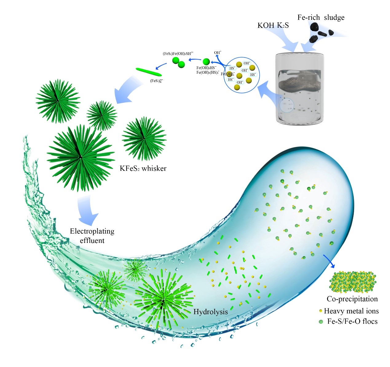
KFeS2 whisker had a one-dimensional linear structure, in which an Fe atom was coordinated with four S atoms. It was stable in alkaline solution at pH > 13.6 and commonly formed in strong alkaline solution as follows. Firstly, when Fe3+ was added in the alkaline solution, it was rapidly polymerised to form Fe-bearing precipitates in weakly crystallised form. The sludge acquired from the cold-rolling company showed a similar characterisation to the Fe-bearing precipitates; a small portion of carbon was from the dropped emulsion oil [25]. With the addition of KOH and the hydrolysis of K2S, free OH- was abundantly generated in the solution and then eroded the surface Fe of sludge to generate and release Fe(OH)4- into the solution. Accordingly, the Fe concentration increased in the supernatant. Fig. 9 shows that Fe was 0.045 mg/L at pH 7 and rapidly increased to 5.595 mg/L at pH 15.6, suggesting the dissolution of Fe-bearing precipitates and sludge in strong alkaline solution. Secondly, free SH- was generated at mass production from the hydrolysis of K2S and then spontaneously replaced OH- of free Fe(OH)4- to form Fe(OH)3HS-. The replacement reaction continued, where Fe/S-bearing products, e.g. Fe(OH)3HS- and Fe(OH)2(HS)2-, were generated. Thirdly, the conjunction reaction between two newly formed Fe/S-bearing products occurred to form (FeS2)Fe(OH)3HS2-. Such products were sparingly soluble in alkaline solution and precipitated from the solution. Fig. 9 shows that Fe was residual at 0.184 mg/L in the supernatant after the reaction; this residual level was lower than that in pure KOH solution, demonstrating that Fe/S-bearing products were formed and spontaneously precipitated from the solution. The conjunction reaction continued, which accelerated the polymerisation of Fe/S-bearing products, with the generation of linear (FeS2)nn- as the final product. Fourthly, in the (FeS2)nn- structure, the negative charge was neutralised by free K+, resulting in the formation of one-dimensional KFeS2 whisker.
Impure carbon was not involved in KFeS2 synthesis and did not accumulate in the supernatant. After the reaction, the supernatant was alkaline and rich in HS-, which could serve as a cyclable resource to prepare KFeS2 with supplementary K2S and KOH. Thus, the dosage of K2S and KOH was considerably reduced. Temperature was an important parameter in KFeS2 synthesis. As the temperature rises from 50 °C to 80 °C, both the reaction between OH- and surface Fe of sludge and the release of Fe(OH)4- to solution accelerated, which employed sufficient Fe(OH)4- for the polymerisation and crystallisation of KFeS2 whisker. Accordingly, high temperature was an important route to reduce the reaction time. For instance, linear KFeS2 particles were generated after hydrothermal treatment at 190 °C for 18 h [9]. The drawback of high-temperature treatment in water was the formation of hematite from the rapid polymerisation of the surface Fe-OH group of sludge [9, 26, 27].
Before the application in wastewater treatment, the storage of KFeS2 was a key step. Wet KFeS2 particles remained stable for a week and showed a similar effect to freeze-dried KFeS2 in the removal of heavy metals from effluent. Besides wet storage, vacuum-drying could also function as an alternative method for KFeS2 storage, where the dried product showed a similar effect in Zn/Ni removal to freeze-drying. In the air-drying process, the redox reaction between oxygen and structural S of KFeS2 occurred. This phenomenon led to the consumption of KFeS2 and accordingly decreased the Zn/Ni removal efficiency in comparison with the freeze-drying method.
In the effluent, heavy metals were complexed with organics to form stable organic-heavy metal ligands, so that they were refractory to be removed even though the precipitates (e.g. lime and polymeric ferric sulfuric) were added. When KFeS2 was added in the electroplating effluent, it was spontaneously decomposed to generate Fe/S-bearing flocs with numerous Fe-SH and Fe-OH groups [28]. Such flocs were negatively charged (Fig. 11(a)) and had an average hydrodynamic radius of 600 nm (Fig. 11(b)). Subsequently, heavy metals, e.g. Zn and Ni, were coordinated onto the Fe-S/Fe-O groups, resulting in the removal of Zn/Ni from effluent. In comparison with the hydroxyl group, the new -SH group had strong affinity to complex with heavy metals, because S had a bigger atomic radium than O and was more electronegative to from the -S-Me group than O [29]. After heavy metal adsorption, the zeta potential of flocs apparently increased from -50 mV to -35 mV, where its radium considerably increased to 3500 nm, demonstrating the polymerisation of flocs in the adsorption of Zn/Ni. Floc polymerisation continued when stirring was slow and/or stopped, resulting in the generation of heavy metal-bearing sludge.
3.7 Environmental application
The conversion of cold-rolling sludge to KFeS2 was performed at pilot scale, and the product KFeS2 whisker showed superior efficiency in the treatment of real electroplating effluent contain Zn/Ni. The total cost of KFeS2 synthesis was calculated as shown in Table 1. To reutilise 1 ton of sludge with the recycling of supernatant, approximately 0.22 tons of K2S, 0.33 tons of KOH and 0.5 tons of water were consumed, along with the electric power of 18.6 kWh, which amounted to a total cost of US$ 294.9. However, about US$373.3 was spent in the disposal of 1 ton of sludge [30], and this amount can be deducted from the total cost of KFeS2 synthesis. The KFeS2-bearing product was marketable due to its performance in electroplating wastewater treatment, and it cost US$242.9/ton in accordance with the price of polymeric ferric sulphate. Therefore, the recycling of cold-rolling sludge as KFeS2-bearing product was profitable.
Table 1
Total cost of cold-rolling sludge to KFeS2 synthesis
| |
Reagent and processing
|
Price (US$)
|
Usage/ton
|
Total price (US$/ton)
|
|
Sludge disposal
|
Transport, solidification and landfill
|
373.3/ton
|
|
373.3
|
|
KFeS2 Synthesis
|
Tap water
|
0.28/ton
|
0.5
|
0.14
|
|
K2S
|
673.3
|
0.22
|
148.126
|
|
KOH
|
432.5
|
0.33
|
142.725
|
|
Pulping power
|
0.21/kWh
|
0.6 kWh (total 1 h)
|
0.126
|
|
Reaction power
|
0.21/kWh
|
18 h (total 24 h)
|
3.78
|
|
Product income
|
KFeS2 product
|
|
|
242.9
|
Other Fe3+-bearing sludge was also produced as solid waste in the steel-making, dye chemical, and mineral industries; it could function as an Fe3+-bearing resource to be recycled as KFeS2 whisker. Such recycling not only saved the disposal cost of sludge but also produced new Fe/S-bearing product, thereby exhibiting acceptable application in these industries.