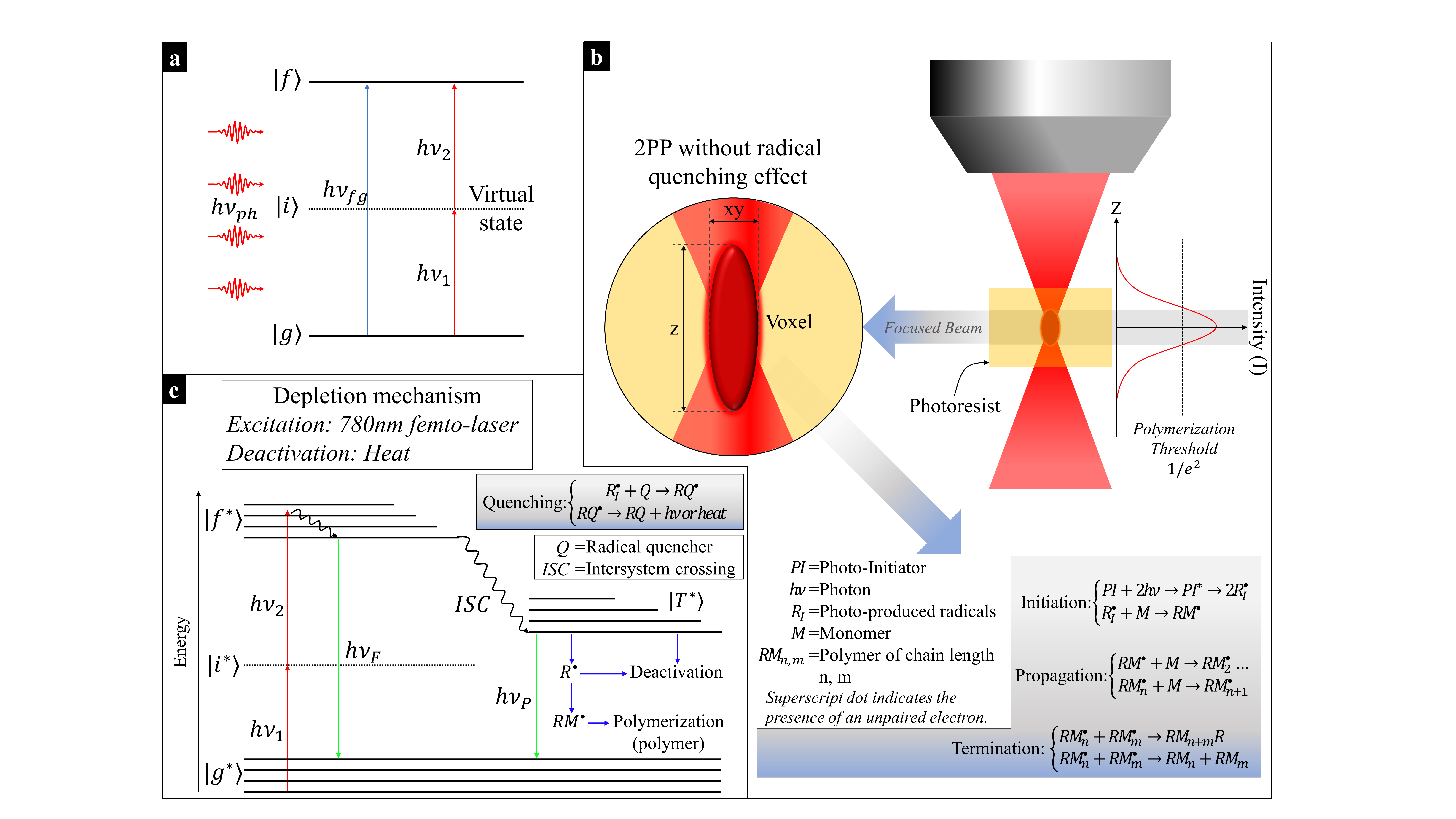
Alignment patterns with a pitch (Pt) of 1 µm and a linewidth (A) of ~ 0.5µm in 25×25 µm2 area per pattern as shown in Fig. 3a were employed. The chosen line aspect ratio, width and pitch has previously been employed in the group for nano-imprint alignment of LC. The lines of a printed pattern were generated using vectorial plotting at any given alignment angles (φ) resulting in nicely defined structures as seen in Fig. 2.
Cells with dichroic dye-doped LC, mounted as sketched in Fig. 3a, scale transmission images when linearly polarized light is incident on the 2PP-patterned surface. The uniformly rubbed surface, with known LC alignment direction, permitted the confirmation that absorbing polarization and the LC director coincided. When then alignment angle of the LC (φ), and thus the guest dichroic dye, coincides with that of incident light polarization, minimum light will be transmitted44, while if the incident polarization is perpendicular to the alignment angle a maximum of light will be transmitted. For any other φ an intermediate fraction of the light will be transmitted. This observation also allowed for an absolute alignment direction assignment of the LC molecules on the nanostructures.
In all the below figures, LC alignment angle (φ) is indicated, not the light transmitted by the LC.
SU-8 photoresist
In this study, 10 distinct patterns of parallel lines have been defined and printed under identical conditions. Each pattern, n, is characterized by an alignment angle \({\phi }_{n}=\left(\frac{\pi }{18}\right)\times \left\{(n-1)|1\le n\le 10\right\}\), as shown in Fig. 3b. The 10 different \({\phi }_{n}\) values result in varying light transmission of the assembled cell when illuminated by linearly polarized white light from the patterned side. The nanostructured texture is reflected in visible variations in the light transmission, confirming that the dye and LC are aligning parallel to the engraved lines, as seen in previous studies26,27.
The 2PP structure in SU-8 exhibits good alignment of the LC with a high repeatability in all directions uniformly across the individual alignment patterns (Fig. 3b-c). In Fig. 3d, a patterned polarizer with patterns arranged in a chessboard-like configuration is shown, together with ascending/descending grayscales. A visible edge between adjacent patterns can be appreciated, corresponding to the inter pattern space in the design as seen in Fig. 3a.
The quality of the patterned polarizers in the LC cells has been quantified by the contrast ratio (CR)21. The transmitted light intensities were quantified using a NIKON D3400 camera configured with sensibility ISO-400, with exposure time of 1/125 s and 1/30 s. Subtracting the average minimum intensity transmitted by the standard crossed polarizers (P⊥), denoted as (\({\stackrel{-}{I}}_{bkgr}\)), with the microscope precisely focused onto a glass surface, the following CR was calculated:
$$CR = \left({\stackrel{-}{I}}_{max,meas}- {\stackrel{-}{I}}_{bkgr}\right)/\left({\stackrel{-}{I}}_{min,meas} - {\stackrel{-}{I}}_{bkgr}\right)$$
1
where \({\stackrel{-}{I}}_{max,meas}\) is the average transmitted light intensity by the brightest pattern, and \({\stackrel{-}{I}}_{min,meas}\) is the minimum average transmitted light intensity by the darkest pattern. This resulted in a normalized CR of 14 for SU-8.
The uniformity, i.e. quality, of the alignment of the pattern in the LC cells has been analyzed by employing image entropy (H)45. This parameter measures the disorder in the intensity distribution and provides insights into uniformity of the molecular orientation within the grooves formed after 2PP-DLW. The disorder is calculated using the Shannon expression:
$$S\left(I\right)=\sum _{I=0}^{N}P\left(I\right)\times {{log}}_{2}\left(P\left(I\right)\right)$$
2
where P(I) is the probability of the occurrence of intensity I within the pixel pattern area and N is the number of intensities measured within the same pixel pattern area.
Where, the uniformity distribution is normalized, dividing the S(I) computed as disorder measured by the maximum entropy of pixel pattern \(max\left(S\left(I\right)\right)\) when all intensities are equally likely to occur (\(P\left(I\right)=1/N\)). Thus (2) becomes:
$$H\left(I\right)=-\frac{S\left(I\right)}{{{log}}_{2}\left(N\right)}\times 100\%$$
3
Here, H ≈ 0% denotes perfect uniformity, while H ≈ 100% a random intensity variation of the pixels in the image. Figure 4 shows that the uniformity of each of the 10-pixel patterns. All the patterns show similar disorder under both parallel and crossed polarization, although each introduce a different twist in the LC cell, indicating a strong azimuthal anchoring.
H was calculated over an area of 25x25 µm2 corresponding to 200×200 pixels2 per pattern. The degree of disorder H is approximately 35%, representing around 65% of the uniformity of the grayscale alignments. All measured patterns had a variability of approximately 8.8%, highlighting the robustness of the alignment technique, and illustrating a low uniformity distribution with a standard deviation (StDev) of ± 3.1.
S1805 photoresist
The same cell structure and analysis have been performed on S1805. In Fig. 5, the LC alignment of a patterned polarizer with S1805 is shown. In this case a 3.2×3.2 mm2 logotype of CEMDATIC has been patterned instead of the checkerboard structure. The alignment of the LC molecules and dye is parallel to the orientation of the grooves cut in the S1805.
Figure 5a shows photos of the dichroic dye-doped LC cell backlit with polarized light incident onto the uniformly rubbed and patterned alignment surfaces respectively. The discrete 2PP aligned areas are clearly visible, with a visibly high contrast. In Fig. 5b, the original pixelated image and measurements of the transmitted light intensities in the doped cell are shown with the incident light polarization parallel to the alignment direction in the text (appearing dark text on bright background) or perpendicular hereto (appearing bright text on dark background). The normalized contrast ratio (CR) was of 37 for the measurements using (1).
As above the normalized Shannon entropy (H) of the intensity distribution of grayscale patterns, has been used to assess the alignment quality. In this case H was also calculated over an area of 25x25 µm2 (200×200 pixels2/pattern).
Figure 5: Analysis of LC alignment fabricated in S1805. a) Photos taken of the sample backlit with polarized light. Left: Light incident onto the uniformly rubbed surface. Middle and Right: Light incident onto the patterned surface, where recognizable features are clearly visible in separate aligned regions. b) Original logotype used in the LC cell, and micrograph with a standard polarizer placed in parallel (P||) and crossed (P⊥). The blue dashed lines indicate standard polarizer (P) direction, red line indicate the rubbing direction (RD) of the polyimide and yellow dashed lines indicate the alignment angle (φ) patterns. c) Grayscale pattern entropy (H) of LC cell in S1805 aligned patterned polarizer.
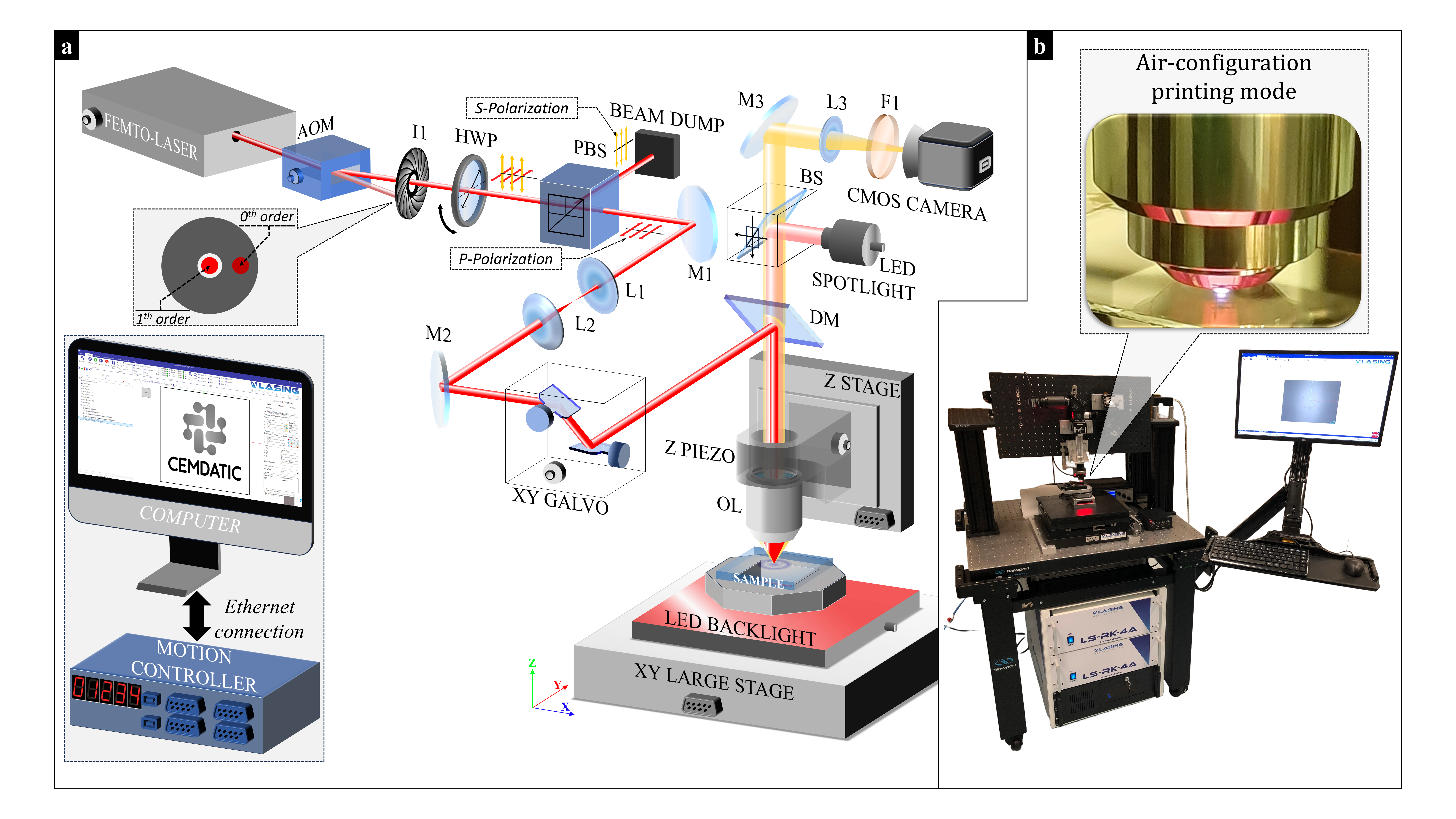
S1805 is an option for creating patterned polarizers in doped LCs. The patterning processes in large-sized LC cells is significantly faster in S1805 due to its high photo sensitivity (62 min of 2PP-DLW processing at a scanning speed of 6 mm/s) compared to SU-8 for the same CEMDATIC logotype (205 min at 1 mm/s).
Table 2
Alignment quality comparison (CR and H) for both SU-8 and S1805 alignment surface.
| Alignment Quality | SU-8 alignment | S1805 alignment |
| Normalized CR | 14 | 37 |
| Entropy (H) | 35 ± 3.1% 65% of uniformity | 37 ± 5.3% 63% of uniformity |