A massive BDs deposition on the common rectangular flat plate (RFP) of photovoltaic (PV) module is a matter of great concern in Western Rajasthan (WR) that diminish the overall energy production capacity of the system remarkably. In this research article, a prototype NFP design of a front glass cover of PV module is proposed to prevent the impact of BD settlement by the restriction of bird’s sitting/movement on the front glass cover. In this regard, the performance analysis of PV module with common RFP and newly designed NFP glass covers has been assessed at the different inclination β° (0- 90). The BD accumulation onto the both glass cover explored by the optical transmittance profiles at the different tilt angles, i.e., explained by bird movement on each flat glass surfaces. Consequently, a significant amount of output electric energy has been gained in NFP design rather than RFP corresponding to particular tilt regions TR I (0° ≤ β ≤ 25°), TR II (25° ≤ β ≤ 60°), and TR III (60° ≤ β ≤ 90°). According to the results achieved, an excellent level of improvement in average power loss, ~ 97.85%, corresponding to optimal TR(III) has been detected by employing NFP glass collector.
Research Article
Performance Enhancement of Solar Photovoltaic (PV) Module Using a Novel Flat Plate (NFP) Glass Cover by Reducing the Effect of Bird Dropping (BD) Settlement
https://doi.org/10.21203/rs.3.rs-437395/v1
This work is licensed under a CC BY 4.0 License
Journal Publication
published 26 Aug, 2021
Read the published version in Environmental Science and Pollution Research →
You are reading this latest preprint version
Bird dropping (BD) deposition
PV module soiling
novel flat plate (NFP) design
Power loss
Western Rajasthan (WR)
The accumulation of BDs on a flat plate PV collector worsens the situation that additionally diminishes the performance of a solar PV module day by day, especially in the climatic conditions of WR (N24° 37' 00" to N30° 10' 48" / E69° 29' 00" to E76° 05' 33") commonly which is characterized by its “high rate of dust deposition” and “small frequency (10.4–20.5 days in a year) of rainfall with poor intensity” in a year (Singh et al. 2005). An enormous settlement of BDs and dust fouling (i.e., “soiling”) on a flat glass cover of the PV module, is a critical challenge for the sustainability of output solar power generation capacity of PV systems in the Western desert region (i.e., “Thar”) throughout the year (Fig. 1).
Partial shading (i.e., non-uniform illumination) due to surrounding fixed objects like building, tower, tree, and passing clouds (i.e., dynamic shadow) is a key issue that strongly affects the overall performance and decide the life of a solar PV plant. In addition, the deposition of surrounding location and environment related fine dust particles like as salt, plant products, debris, soot and BD (i.e.,static shadow) on the surface of PV module are promptly observed (Mekhilef et al. 2012; Appels et al. 2013; Maghami et al. 2016; Said et al. 2018; Smestad et al. 2020) in daily examples. Common soling factors like fallen leaves, BDs, water streaking can be reduced the energy efficiency upto 10–30% additionally (Dabhi et al. 2017) as well. Furthermore, the dirt deposition can be also in a main aggressive form of the biological contamination ‘BD’. Therefore, it is commonly pointed out that BDs (guano) is one of the main contaminated source of soiling on PV systems that reduce a more electric energy output (Kalogirou et al. 2013; Cano et al. 2014; Xu et al. 2017; Hanifi et al. 2019). In this context, it has been widely noticed that perching birds carry small dust particles and dropping matters sediment by their feet and body (Reheis and Kihl 1995). When sunlight strikes on a front glass plate of PV module, it absorbs, scatters, and reflected back by dirt particles and drastically reduces the intensity of transmitting light that incident on the active portion of the PV module (Yfantis and Fayed 2014; Pedersen 2015). In feature, BDs matter is fairly opaque and can adversely affect the optical performance (i.e., transmission of sunlight) of the PV system (Ghazi et al. 2014; Ghosh and Neogi 2016; Bingöl and Özkaya 2018). A thick layer of accumulated BDs matter is an example of uneven soiling that leads to hard shading conditions on PV system and it forms static shading that concern to localized degradation of PV modules (Wohlgemuth et al. 2013; Pettersen 2015). Furthermore, the affected portion of the PV glass cover persists shaded for longtime until washed properly (Sayyah et al. 2014). As Bana and Saini (2017) demonstrated the effects of shading caused by various obstacles such as bird litters, tree, pillars and passing clouds considering with the mimic of 14 different kinds of shading patterns. At coastal sites of Lebanon, the presence of birds (seagull) mainly caused by waste dumps in that region (Hammoud et al. 2019). Harrison et al. (2017) discussed the impact of solar farms on birds, bats and general ecology. Moreover, Babatunde et al (2018) commented the significant effect of BD fouling on PV plant (B-Block) i.e., installed at the tilt angle of 15°. It is mostly seen that impact of BD settlement is incredibly cruel than soiling due to fine dust particles and other contamination sources. Hence the practically, complete removal of strongly adheraed BD from system surface will be almost cost effective, particularly for the large-scale PV sites (Al-Jawah 2014).
In another work, 2% reduction in maximum power (Pmax) has been indicated exposure to outside BD conditions (Lmenes et al. 2011). Over time, if BD materials not properly scrubbed on the module surface, heating of the particular shaded area starts that may lead to discolouration and as a result permanent damage appears in the form of hotspots (Chaudhary and Chaturvedi 2017). In thermo-graphic study of PV module, Sharma and Jain (2016) inspected the effects of hotspots, cracks and BDs on PV system. In addition, it is also pointed out that the BD material is much more opaque than other soiling contents like dirt, pollen, dust, etc. With this regard, high instantaneous loss 81% of PV systems with high BDs accumulation was noticed in Chandler, AZ. Whereas high soiling condition concerned with the great amount of BD deposition, in absence of regular rain event for a long time, close to horizontal plane, and low cleaning frequencies (Naeem 2014). The consequences about the effect of BD settlement on PV system have been summarized as in Table 1.
1.1 Bird’s repelling systems
Nowadays a number of efforts have been developed for terrifying and preventing the birds sitting on PV module in various aspects. A number of measures have been employed for scaring and terrifying the birds such as bird spikes, audible bird scares, low-current electric barriers, and nontoxic chemical products (Ballinger and KE 2001; Tate 2010; Hudedmani et al. 2017) widely in practice as listed in Table 2.
A mechanized cleaning (robust structure) system often used to scare off BDs material (Deb and Brahmbhatt 2018). In context of cleaning process, an active self-cleaning system that removes contamination from a PV glass plate based on microsized features and mechanical vibration (Sun and Böhringer 2020). Lamont and Chaar (2011) has also designed an automated electro-mechanical cleaning system controlled by a PLC (Programmable Logic Controller) device for settling BDs in which mechanical system comprised of wipers, night sensor and motion sensors. A 18–20% efficiency has been improved using an automatic microcontroller based vacuum blower (Akbar and Ahmad 2019).
In this perspective, an ultrasonic 1–4kHz, (irritating the birds) based bird deterrent system comprises of frequency scanner; frequency generation, power drive, and transducer alarm (Ogochukwu et al. 2012). An electronic bird repeller is an electronic sound system that emits the sound of a particular frequency which irritates the birds (See Fig. 2a) (Suryawanshi 2014; Muminov et al. 2017; Baral et al. 2019). A more common way to frighten the birds can be helped by “scare crow” discouraging the birds from nesting and sitting on PV module as shown in Fig. 2b (Mondal and Bansal 2015; Król et al. 2019). In general, a very common tactic is used for keeping the birds away from the device, installing either metal or polycarbonate spikes on the metal frame of PV module as presented in Fig. 2c (Cano 2011; Naeem 2014).
As above mentioned, it can be commonly seen that only the limited work has been attended in contaxt to the prevention of BD contamination on the PV glazing surface worldwide so far.
A numerous types of common shadow effects are to be associated with the birds sitting/walking tenacity and their impact of BD deposition habit on the PV module surface in different aspects, i.e., responsible for diminishing the sunlight transmittivity by negative effects such as “the covering by BDs deposition” (i.e., blocking the sun radiation by covered area), “dynamic shadow caused by bird’s movement” (i.e., by sitting/walking of birds on the front PV glass surface and its metal frame also), “self-shadow of dropping materials”, and due to “splashing of urine fluid slope down to the PV glass surface” as illustrated in Fig. 3.
Moreover, settled bird’s poop material strongly attracts the smallest dust particles and promotes more dust accumulation on over itself that leads to more power loss and as final result; critically disturb the panel’s operational life and its DC power output. For this purpose, the characterization study regarding the effect of BD deposition on PV front glass cover is essentially part of the study to understanding about the poop.
There are mostly found shapes of BD material (i.e. scoop, circular tube and flatter pattern ) and sizes (~ 3–6 cm) deposited (i.e., strongly stuck) in bulk amount over the smooth glass surface of PV module as shown in Fig. 4. The bird’s faecal matter is mainly composed of quartz (SiO2) with some alkali and alkaline earth metals.
3.1. scanning electron microscopy – energy dispersive spectroscopy (SEM-EDS) analysis of BD
In the detailed characterization study of faecal matter, the morphological and elemental analysis is performed using a SEM-EDX (BRUKER) technique. In which the dried BDs sample collected from PV glass surface and then material is ground using an agate mortar pestle to obtain the samples in the form of fine powder. A route diagram of sample preparation for the characterization is shown as in Fig. 5 below.
The images of SEM-EDX analysis of collected BD material from the PV module glass plate has been presented in Fig. 5. The obtained results of SEM-EDX analysis indicates the BD sample contains most common found elements in poops (guano) as alkali (Na, K) and alkaline (Ca, Mg) earth metals mixed up with some other elements aluminium (Al), Iron (Fe), & Silicon (Si). Presence of Si (small dust particles) confirms the bird intake small piece of stone (Pebbles) in their diet. Moreover, the presence of small dust particles in depositing faecal matter leads to itching (i.e., scratching of PV glass surface) the smooth glass surface during regular cleaning process of PV glass surface. A longtime effect, results in an increase of the blurriness (optical aberration) of the glass surface and hence reducing the intensity of sunlight across a PV module glass surface. All these particles are randomly allocated and “Needle like” structure examined in the SEM results that attributes the formation of humidity containing soluble or partially soluble deposited BDs material became dried up (i.e., cementation of matter) (Mehmood et al. 2017; Ilse et al. 2018). These structures attribute the tendency of link (i.e., adhesion by air moisture capturing) between the dropping particles and PV glass surface is primarily made by needles (Ilse et al. 2016).
Once the hydrated BD material gets dries under the action of sun heating then it becomes hard (sticky) and difficult to remove from the smooth glass surface of PV module as a result of ‘cementation’ process (i.e., strongly adhered to the solid glass surface) as depicted in Fig. 6 (Sarver et al. 2013; Hassan et al. 2016). In practice, the water dissolved ions (Na+, K+, Ca+ 2) attract undissolved BD’s particles (semi-solid) due to electrostatic and ionic bonding force and increasing the adhesion strength (Adukwu et al. 2020). These ions enter into the hydrated layer of BD matter and hold them together during the water evaporation under the action of sun heating (Yilbas et al. 2015; Abdelmajid 2016; Yilbas et al. 2017). At the same time action of surface tension concerns to the interaction between the BDs and present water molecules in void space of the solid matter is to be deposited over the glass surface of panel. This effect concern to meniscus forces which produces the dust cluster and scale-up the adhesion strength in between the dust particles and PV glass surface (Cuddihy 1980; Kempe 2006; Moutinho et al. 2017).
3.2. Dropping cleaning time (Removal time of BD components)
As it is mainly seen that the faecal material is more adhere to the glass surface of the PV module rather than dust particles. Even though, a vacuum cleaner is also not able to remove (i.e., can’t easily detech the solid poop’s matter from smooth glass surface) the BDs material from the glass surface of PV module (Boeing 2018). Sometimes, a rigorous rain event cannot be enough to wash away the BDs from glazing surface of PV system completely (Cano 2011; Solórzano and Egido 2013; Thevenard 2013) and as such, electrical performance losses due to BDs cannot entirely restore after small rainfall events (Kumar et al. 2013). Therefore a regular wet or dry manual cleaning of PV glass surface is essentially needed. Hence the BD deposition may have some serious effects comparatively to dust settlement (Mani and Pillai 2010). Consequently, the great amount of water will demanded either by manual or automatic cleaning for complete removal of the strongly adhered dropping matter from the PV surface. As an approximate assessment, ten gallons of water required for the cleaning work in about 15 minutes. The estimated water consumption is to be 1.98 litre/m2 (Naeem 2014).
Therefore, in order to check out the adherence (stickiness) of dropping material to the smooth glass surface, a simple lab test is conducted in the laboratory for simulating the effect of cleaning time of various adhered phases of BDs matter due to rain event as shown in Fig. 7.
With this regard, it is usually observed that in the beginning of cleaning process, initially deposited dust particles are removed and then less sticky green part of BD material is to be easily detached from the smooth glass surface, while white-creamy part (i.e., dried uric acid, C5H4N4O3 more adhere with the glass surface) is still adhered with the glass surface and it takes much more time to wash off completely from the PV module plate as shown in Fig. 8.
It is commonly seen the birds excrete nitrogenous wastes in the form of uric acid (viscous and mucoid) and it doesn’t easily dissolve in water (Balogh 2017). Hence its capability to stick onto the PV module glass cover strongly like drops of white plaster. Uric acid is a hetrocyclic compound of Carbon (C), Nitrogen (N), Oxygen (O), and Hydrogen (H); and the pH level of uric acid lies in between 3.0 and 4.5 (quite acidic) (Vasiliu and Buruiana 2010; Wandah 2010). In which, the pH level matter also affects the adhesion process significantly, i.e., adhesion strength between the accumulated solution (i.e., white paste of hydrated BD matter) onto PV glass surface varies with the pH of the solution (Somasundaran et al. 2005).
As well as this, it is commonly evident that white creamy part of acidic BD material stays even (i.e., strong adhesive) on the panel’s surface after a rigorous rain event for a longtime. Eventually, it is almost predicted that an appropriate intensity of rainfall is frequently required to clean the complete PV module glass cover from soiling off.
As overall, a high intensity level of rainfall will be continuously required to clean up the entire module glass cover. Meanwhile, in case of dust removal, only a less amount of rainfall is needed. Especially in winter season, a very little rain event quickly promotes the BD accumulation during the period from October to February (i.e., critical BD deposition period/Winter) in WR and can cause extensive power drop in this time period.
4.1. Description of novel design structure
Currently, installation of a regular RFP collector technology at fixed tilt angle and orientation in portrait mode is very common in practice worldwide. Occurrence of biological BD contamination on the front glass collector of a PV module is a crucial factor, especially in a desert zone which leads to an additional reduction in power generation capacity of PV system. For solving this problem of BDs, a prototype NFP design of the front glass surface has been proposed for reducing the effect of BDs deposition on a novel flat plate glass cover as depicted in Fig. 9.
In newly designed structure (NFP), the following steps have been considered for reducing the adverse effects of BDs settlement on PV glass surface based on restricting the sitting/movement of birds on the smooth front glass cover:
- In first step, the upper side of a PV glass plate has to be shaped into an isosceles triangle for avoiding the “bird sitting” on it. For this specific designing purpose, the internal angles (θ°) of both equal sides of the triangle kept minimum as ~45° considered ( 9). This particular side angle of θ° (~45) will support to constraint the bird’s sitting/movement on upper angled sides, especially at high inclination β° (>60) of the plate.
- In addition to the first step, around ~5 cm of the upper glass strip of equal angled sides is kept free from back support for maintaining only the thickness of the glass plate (~2mm) as shown in 10a. For thin glass strip, metallic and some other polycarbonate type hard materials can be used on the place of glass optionally. The key usefulness of this idea is to prevent the “gripping of a bird’s claw” with upper angled sides of “the smooth thin glass strip” and its result is that birds will be unable to sit on it (i.e slip down). In general, it is mostly pointed out that all common RFP PV modules is bounded by a ~1mm thick, L-shape aluminium metal frame with ΓV vertical component of ~3.5cm which offers an appropriate space for the bird’s movement/sitting along the upper side of the metal frame at the high inclination as presented in Fig. 10b.
4.2 Electrical performance analysis
In an experimental measurement, a reduction in output power of PV system caused by BD settlement has been assessed. In this regard, we have considered a set of transparent glass plates of the RFP and NFP design structure for the output electrical power assessment. These glass plates (i.e., RFP and NFP) were exposed to BDs at different tilt angles (TA) in a natural outside experiment condition for the PV performance evaluation. For this purpose eleven identical ~2mm thick RFP and NFP designed glass covers were considered for the experimental investigation. The glass plate collectors were fixed with eleven TA (β) (0° to 90°) at ten-degree increments from horizontal to vertical position, where the TA of glass cover considered from the horizontal direction. In interest, one of the glass plate is placed at a specific angle, approx. 25°5´ (common yearly), which is the optimum fixed tilt angle of the PV module installation in WR. All glass covers were fixed on a wooden based structure of different inclinations (0° to 90°) as shown in Fig.11.
4.2.1 Electrical experimental description
The experimental work is completed by attaching the exposed BD glass plates to a reference solar PV module (40-W, Ritika RSPL12P40) as shown in Fig. 12. The test PV system comprises of a standard silicon solar module of area 2511 cm2 (15.5 cm × 4.5 cm/array of 36 series connected cells as 9 × 4 serial configuration strings) and the professional solar wattmeter (Solar Module Analyzer PROVA 210) is used for assessing the PV output. Output electric data collected every week, frequently measured under the natural sunlight for the evaluation of PV output. The data were recorded manually with a clean module glass cover and after that with an exposed BDs plates.
A full experimental study was executed on a terrace of building located in the Jodhpur region (26.91° N, 70.90 E / WR) over a time of four months (from December to March) during critical BD deposition period (i.e., a Winter season). After deposition of faecal material (i.e., exposed glass plate of the RFP and NFP at different inclination) on glass collector, the monthly average data have been collected as fast as likely on clear shiny (sunny) days. As result, the outcome of BDs can be assessed in term of power losses (%) by comparing maximum output power Pmax (i.e., Pmpp) before (clean/ without BD) and after (dirtied / with BD-exposed glass plates) contamination by using Solar Module Analyzer PROVA 210 stated as follows (Sulaiman 2014; Sun 2014) as presented in Fig. 13.

4.3 Optical performance analysis
In optical performance analysis, the normal transmittance measurement across the BD contaminated novel designed glass structure has been assessed. As a result, the “BD pattern” (i.e., the spatial distribution of BDs deposition) has been obtained for demonstrating the effect of BD settlement over the RFP and NFP glass plate at different inclinations. In this regard, the intensity of transmitting light across the dropping-contaminated NFP glass samples was studied using a solar power meter. In this method, the exposed glass plates were exposed at the different TA (β), from low inclination (horizontal/0°) to high inclination (vertical/90°) directed, for four months from December to March (winter) (Nahar and Gupta 1990; Elminir et al. 2006; Sisodia and Mathur 2019).
4.3.1 Optical experimental description
The optical performance is evaluated by the transmittance measurement (i.e., transmittance profile) of BD contaminated NFP glass design. The normal transmittance measurements through the contaminated glass covers were carried out in the laboratory with the experimental setup as shown in Fig. 14a. The experimental setup consists of a yellow halogen light (equivalent to sunlight) source of visible spectra (555 nm) range, convex lens, and dirtied glass plate samples, patterned in square shaped section (patch) of area (4cm×4cm). Concerning this, the average transmittance intensity, ΔT (%) of halogen light (W/m2) was measured by using a MECO solar power meter (Rao et al. 2014; Sisodia and mathur 2020) across to each patch as depicted in Fig. 14b. A significant fall in intensity of transmitting radiation causing the bird’s dropping can be calculated by the output transmittance losses (%) as follows:

4.3.2 The influence of BD settlement on transmittance losses (%) corresponding to RFP and NFP structure at different TA(β)
In this regard, an average transmittance loss (ΔT %) with the location (i.e., area of plate) on the RFP and NFP exposed samples has been plotted (i.e., called “BD profile”) corresponding to different TRs (i.e., I, II, and III) to describe the effect of spatial settlement of BD on to the RFP and NFP glass covers. In fact, obtained transmittance profile depicts the direct results of the bird’s movement (i.e., sitting/walking behaviour) on the flat glass surface as shown in Fig.15 a-c.
As considered experimental results, the effect of BD settlement on RFP and NFP designed structure has been represented by an output electrical study (i.e., power loss, ΔP%) at the different TA (β). Afterward, these obtained results were also explained by the transmittance study (i.e., transmittance losses, ΔT%) of BD deposition patterns (settlement of BD on the flat glass cover space, i.e., “dropping pattern”) categorized corresponding to three different inclined regions (i.e., a region TR I, TR II, and TR III).
5.1 The effect of BD deposition on RFP and NFP design structure on solar power output (%) with different TA (β°)
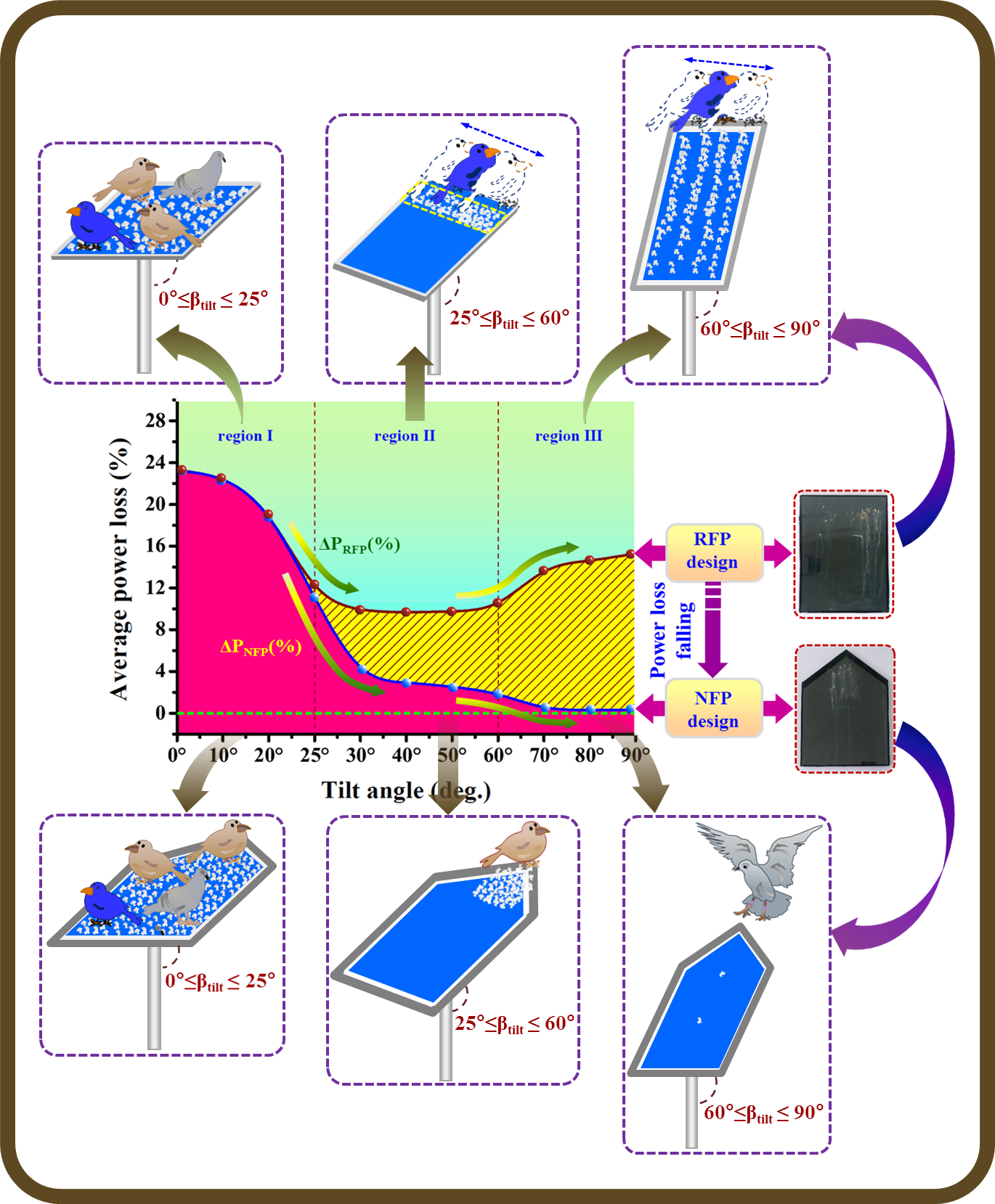
The effect of BDs contamination on the RFP and NFP designed structure has been determined in terms of average power losses (ΔP%) at different TA (β°). The obtained results show a significant reduction in output power loss (%) due to BD phenomena onto the set of eleven TA (0° to 90°) for both designs (i.e., RFP and NFP). The particular observed results and study can be analyzed into three specific TRs corresponding to different inclinations, i.e., a TR I (0° to 25°), TR II (25° to 60°), and TR III (60° to 90°) as indicated in Fig.16.
In TR I (0° to 25°), it is pointed out that a critical reduction in output power has been observed for both types (i.e., RFP and NFP structure) of contaminated glass cover at the inclination 0° (i.e., close to horizontal way) due to great deposition of BD material rather than other tilt configuration listed as in Table 3. Moreover, it is also fairly pointed out that almost the same average power losses have been detected for both design structure, i.e., 19.21% for RFP and 19.17 for NFP. Because, in this horizontal position of glass cover, birds can easily move/walk over entire the surface area in the same manner on the both plate structures. Now with TR II (25° to 60°), a significant change in average power loss has been noticed, i.e., 19.21 to 9.77% for RFP and 19.17 to 2.67% of the NFP glass surface across the border of TR I / TR II i.e., β° (~ 25) which is termed as “threshold tilt angle (βthr)”as shown in Fig. 16. In TR II, a 9.77% reduction in the RFP design has been measured while 2.67 % for NFP designs structure. In contrast, it is well noticed that a suitable improvement (2.67 %) in output power has been detected out for NFP design structure as compared to the RFP design (9.77%). Finally, a very good progress has been observed 2.67% to 0.316% for NFP glass cover across the boundary of TR II/TR III. Meanwhile, a great power loss has been again progressing 9.77% to 14.68 for the RFP glass plate which is explained by the tendency of bird’s sitting/movement at the upper side of the common RFP surface. Because, in RFP, it widely noted in nature that birds have always a common habit to walk/sit along the upper straight side (i.e., towards the slop up side) and the traditional aluminium frame (L-shape) of PV module offers a suitable space where they can simply grip the metal frame edge at any inclination (β°) as shown in Fig. 10b and 17.
5.2 Bird movement (BD process) on NFP designed glass surface at different inclinations (β)
It was definitely seen that the different obtained “BD patterns” of the RFP and NFP glass plates at different slops β described as the tendency of bird’s movement over the front glass surface of PV module. In this regarding, it is also commonly noticed that birds have the general tenacity to easy walk on the flat surface and move towards the slope up side. Moreover, they also like to sit where they can easily grip the object by their claws (Isaksson 2008). A significant difference in technical characteristics (i.e., output power and transmittance) has been noticed in between both design structures (RFP and NFP) which was explained by the BD deposition phenomenon on both types of glass covers. Hence, outcome regarding the phenomenon of BD contamination over NFP and RFP design is directly associated with the walking/sitting tendency of bird on the surface which is characterized as follows:
5.2.1 Close to horizontal plane (small inclination) / TR I (0° ≤ β ≤ 25°):
In this tilt region, an utmost BD stores on the entire PV glass surface of the RFP and NFP designs. In this regarding, it is widely noticed that birds are capable to simply move over the entire glazing surface without any restrain and hence, resulting the random deposition of BDs in the same manner on the complete glass cover of the RFP and NFP designs. In this situation (TR I), same response of birds has been noticed corresponding to both glass cover (RFP and NFP). Hence, an almost relatively the similar reduction in average output power loss (ΔP%) has been evaluated 19.21% and 19.17% for RFP and NFP designs respectively in TR I. A BDs deposition phenomena and their corresponding exposed NFP design glass plate is illustrated in Fig. 18.
5.2.2 Above-threshold inclination (moderate inclination) / TR II (25° ≤ β ≤ 60°):
As inclination changes from TR I to II (i.e., across the boundary, β : 25°), now the BD accumulation starts to fall rapidly due to confinement of bird’s movement (i.e., a restriction of bird’s movement) on the RFP and NFP glass collectors. A significant fall in average output power loss from 19.21 to 9.77% and 19.17 to 2.67% respectively for the RFP and NFP design glass surface has been observed across the first boundary of the TR I/TR II. As result, It is clearly observed that a good improvement in output power production has been achieved by employing the NFP rather than RFP design at the moderate inclination (region II) where, power loss cuts 9.77% (RFP) to 2.67% (NFP) respectively as depicted in Table 3. Therefore, the main advantage by employing NFP design is, a well improvement “72.67%” in output power reduction has been achieved in this moderate inclination (i.e., TR II).
An abrupt fall in observed power loss (%) is explained by a different sitting/walking behavior of birds on the front glass cover. In this condition, a few BDs deposition localized only on the upper side of the front glass surface. In this contrast, it is usually seen that birds have more chance to sit at the top edge (i.e., birds try to sit at the tip of the plate) of the NFP glass plate, i.e., above the angle of “β° (~25)” (Threshold inclination), birds starts to slip down to the glazing surface and they try to move towards the “upper side” (i.e., towards the slope upside) of the plate as expected by their habit (i.e., birds are always likly to sit at the apex of the object). As result, the falling faecal mterial is only concentrated (localized) at the top edge of the angled sides as depicted in Fig. 19.
Meanwhile, in case of common RFP glass cover, the birds are confined to move along the complete upper straight edge of the PV plate. Hence the obtained dropping pattern consequently appears as a strip-like shape (2–5 inch approx.) on the upper side of PV surface rather than NFP design and the result is that more sunlight is blocked on the upper side of the RFP glass design of module as illustrated in Fig. 17.
Moreover, in the scenario of NFP structure, a significant improvement is seen due to its specific design and construction in comparison to the RFP design. In NFP design, the bird’s movement is to be more restricted in comparison to sitting behaviour on the RFP design. In the following, due to specific structure of NFP glass surface, birds are only capable to sit at the top of the plate (top of the isosceles triangle due to slope made by internal angles(θ) of two equal sides i.e., minimum θ ~ 45°) at the moderate inclination. Consequently, birds will contaminate only the small area (~16×22 cm2) of flat glass cover at the top of the plate as shown in Fig. 19. Hence, its result to a considerable improvement in output power production has been detected in this TR II. This small contaminated area will be same for any size of the NFP glass cover.
5.2.3 Close to vertical (at high inclination) / TR III (60° ≤ β ≤ 90°):
In the study, the most important part is the high inclination (60° ≤ β ≤ 90°/close to vertical) region. In this tilt part, once again more BD settlement takes place onto the RFP photovoltaic surface in which BDs slip down and traverse a long distance due to gravitational effects. Concerning this, BD covers the complete glass surface of the PV system in a specific settlement pattern (i.e., vertically long strip like shape) and its result is that power loss again increases from 9.77 to 14.69% in the case of common RFP glass cover at the high inclination.
But in case of NFP collector, a very insignificant amount (i.e., almost nil BDs) of BD deposition has been traced out on glass surface due to its specific designing and construction during the experimental period. Consequently, a very small average power loss ~ 0.316% has been recorded at the high inclination (i.e., TR III) for a particular plate design (NFP). Hence, the novel design surface works best effectively at the high inclination, i.e., particularly in the region III (60° ≤ β ≤ 90°) due to its explicit design of front glass plate rater than common RFP design surface of PV module.
According to this specific design, internal angles (θ°) of two equal sides, i.e., minimum ~ 45°, offers a well slopes on both equal sides of isosceles triangle which is able to restrict the bird’s movement only on the top edge of NFP glass plate at high inclination. In addition to this, one sees that a strip around ~5 cm on the both upper equal sides of an isosceles triangle is free from back support for maintaining only up to the thickness of the glass (i.e., blade like strip). It is made especially for avoiding the gripping of a bird’s claw to upper slanted edges of the glass plate design as shown in Fig. 20. As a result, with the help of this explicit novel design structure, birds are not able to sit at the tip of the thin glass plate, i.e., the perching birds have been strongly restricted in this TR III (i.e., close to vertical).
It is also commonly known that the sun is lowest in the sky during the winter and higher in summer and energy dropping on a PV module surface can considerably be improved by a suitable change in the plate inclination (β°). It is, therefore, the monthly optimum tilt angle of a PV module is maximum in December (winter) and minimum in May-July (end of summer) in WR as shown in Table 4 (Agarwal et al. 2012; Jamil et al. 2016). According to observed behaviour and study concerning the NFP design, it works more successfully at the high inclination β° (> 60). As mentioned above, the optimum tilt angle is maximum in winter. Asd above mentioned, the particular design (NFP) will be most appropriate in winter season (i.e., also critical BD settlement period in a particular zone) at higher slop to be honest.
The reduction in average transmittance ΔT (%) is measured across to three different inclined regions: TR I (0° ≤ β ≤25°) range from 23.6% to 42.6% (RFP), & 20.7% to 42.4% (NFP); (b) TR II (25° ≤ β ≤ 60°) range from 21.1% to 24.9% (RFP) & 4.1% to 7.1% (NFP); and (c) TR III (60° ≤ β ≤ 90°) 29.5% to 37% (RFP) & 0.5% to 0.8% (NFP) corresponding to both glass plates of PV module respectively as shown in Fig. 21.
A substantial difference in PV losses (%) and transmittance losses (%) for RFP and NFP designs with the inclination (β°) confirms the difference in the effect of BDs on both types of flat glass covers of photovoltaic modules and proves the utility of NFP design. Finally, it can be concluded from the above observation and study of the front NFP glass collector, it works well at the high inclination especially. Hence, the optimal inclination for NFP design β° has the minimum power loss, “0.316%” which is corresponding to TR III (60° ≤ β ≤ 90°) definately. The obtained results of this research work will be helpful for reducing the impact of BDs accumulation on the front glass cover of PV module in the solar field.
This research work has been performed to investigate the effect of biological BD contamination and how can be achieve the performance enhancement by deploying the NFP structure reducing the BD acccumulation in outside environmental conditions without any external consideration. The outcome of this research work shows that a remarkable amount of output power losses (%) has been improved by the application of a novel designed (NFP) structure as compared to common rectangular design (RFP). A relative analysis of output technical characteristic, i.e., output electric power (power losses %) and normal optical (transmittance loss % /dropping patterns) performance in a combination of different tilt angle (β) have been performed to understand the phenomena of BD deposition on both types of the glass covers.
The whole experimental study concerning to RFP and NFP designs has been classified into three different TRs as the low inclination (i.e., close to horizontal / TR I), moderate inclination (i.e., above-threshold angle / TR II), and high inclination (i.e., close to vertical / TR III) explained by the sitting/walking behaviour of birds on both type of glass plate structures. As stated in the case of traditional RFP design, a maximum average power loss (%) and transmittance reduction (%) has been recorded corresponding to TR I, then the minimum in TR II, and it again increases in TR III. But in case of NFP design structure, it decreases continuously with the inclination, i.e., the performance of PV module will improves well with the inclination of plate from horizontal β°(0) to vertical β°(90) progressively.
Based on observed results, it is inferred that a considerable amount of power loss has been reduced corresponding to “72.67%” in TR II ( 25° ≤ β ≤ 60°) and especially at high inclination “97.85%” in TR III ( 60° ≤ β ≤ 90°) by employing a NFP design structure in preference to the common RFP glass plate which really proves the effectiveness and suitability of scientific values of NFP structure at the high inclination. It is, hence, “the optimal inclined region” is TR III (60° ≤ β ≤ 90°) for which the minimum power loss (0.316%) has been recorded due to the least effect of BD deposition on NFP design. Finally, from the experimental study, the following chief recommendations have been planned about the NFP design for their paramount importance as follows:
- First, in this part of NFP, upper side has been shaped into an isosceles triangle with the internal angle of both sides should be minimum as θ ~ 45° for constraint the bird’s sitting/movement on the angled upper edges.
- Additionally, around a ~5 cm of the upper glass strip of equal angled sides is kept blank from back support for maintaining only the thickness of the smooth glass plate (~2mm) to prevent the “gripping of a bird’s claw” with upper angled sides of the smooth thin glass strip.
Hence, a remarkable reduction in average power losses (ΔP%) for NFP glass surface rather than the common RFP design confirms the effectiveness of the newly designed structure to be honest. The consequences of this research study will be useful for improving the PV performance and system life in the field of solar energy installations in outside environmental conditions.
- Ethics approval and consent to participate: “Not applicable” in this section.
- Consent for publication: “Not applicable” in this section.
- Availability of data and materials: All data generated or analysed during this study are included in this published article.
- Competing interests: "The authors declare that they have no competing interests" in this section.
- Funding: No funding from any agencies.
- Authors' contributions:
- Corresponding authors’ (Anil Kumar Sisodia): Experimentation work, data analysis and manuscript preparation.
- Co-author (Ram Kumar Mathur): Supervision and data analysis.
- Acknowledgements:
The author would like to thank for the support and help by Dept of physics, Samrat Prithiviraj Government College, Ajmer affiliated to Maharshi Dayanand Saraswati University, Ajmer (MDSU); and Indian Institute of Technology, Jodhpur (Rajasthan) /INDIA (IITJ).
- Authors' information (optional): Already mentioned.
- Abdelmajid GHH (2016) Chemo-mechanics of dust and mud on protective surfaces. MS Thesis, King Fahd University of petroleum & Minerals, Dhahran, SAUDI ARABIA; 2016
- Adukwu JE, Yilbas BS, Jalilov AS, Al–Qahtani H, Yaqubu M, Abubakar AA, Khaled M (2020) Adhesion characteristics of solution treated environmental dust. Sci Rep 10(1):1–15. https://doi:10.1038/s41598-020-70858-6
- Agarwal A, Vashishtha V, Mishra SN (2019) Comparative approach for the optimization of tilt angle to receive maximum radiation. Int J Eng Res Tech 1:1–9
- Akbar S, Ahmad T (2019) Enhance and maintain efficiency of solar panel using auto cleaning system. Int J Eng Work 6(5):159–163. https://doi:10.34259/ijew.19.605159163
- Al-Jawah MJ (2014) A decision aiding framework for investing in cleaning sys- tems for solar photovoltaic (PV) power plants in arid regions. Dissertation, The George Washington University, ProQuest LLC. 789 East Eisenhower Parkway, P.O. Box 1346 Ann Arbor, MI 48106 – 1346; 2014. UMI Number: 3603229
- Appels R, Lefevr B, Herteleer B, Goverde H, Beerten A, Paesen R, Medts KD, Driesen J, Poortmans J (2013) Effect of soiling on photovoltaic modules. Sol Energy 96:283–291. https://doi.org/10.1016/j.solener.2013.07.017
- Babatunde AA, Abbasoglu S, Senol M (2018) Analysis of the impact of dust, tilt angle and orientation on performance of PV Plants. Renew Sustain Energy Rev 90:1017–1026. https://doi.org/10.1016/j.rser.2018.03.102
- Ballinger KE Jr (2001) Method of deterring birds from plant and structural surfaces, US patent 6,328,986, December 11; 2001
- Balogh K (2017) The effects of bird excrements on copper and bronze. Master Thesis, Czech Technical University in PRAGUE; 2017
- Bana S, Saini RP (2017) Experimental investigation on power output of different photovoltaic array configurations under uniform and partial shading scenarios. Energy 127:438–453. https://doi.org/10.1016/j.energy.2017.03.13
- Baral SS, Swarnkar R, Kothiya AV, Monpara AM, Chavda SK (2019) Bird Repeller – A Review. Int J Curr Microbiol App Sci 8(2):1035–1039. https://doi.org/10.20546/ijcmas.2019.802.121
- Bingöl O, Özkaya B (2018) Analysis and comparison of different PV array configurations under partial shading conditions. Sol Energy 160:336–343. https://doi.org/10.1016/j.solener.2017.12.004
- Boeing AL (2018) The impact of waters of low quality on soiling removal from photovoltaic panels. UNLV Theses, Dissertations, Professional Papers, and Capstones, University of Nevada, Las Vegas; 2018. https://digitalscholarship.unlv.edu/thesesdissertations
- Cano J, John JJ, Tatapudi S, TamizhMani G (2014) Effect of tilt angle on soiling of photovoltaic modules. IEEE 40th Photovoltaic Specialist Conference (PVSC); 2014. https://doi:10.1109/pvsc.2014.6925610
- Cano J (2011) Photovoltaic Modules: Effect of tilt angle on soiling. MS Thesis, Arizona State University, Mesa; 2011
- Chanchangi YN, Ghosh A, Sundaram S, Mallick TK (2020) An analytical indoor experimental study on the effect of soiling on PV, focusing on dust properties and PV surface material. Sol Energy 203:46–68. https://doi.org/10.1016/j.solener.2020.03.089
- Chaudhary AK, Chaturvedi DK (2017) Thermal image analysis and segmentation to study temperature effects of cement and bird deposition on surface of solar panels. Int J Image Graphics Signal Processing 12:12–22. https://doi.org/10.5815/ijigsp.2017.12.02
- Cuddihy EF (1980) Theoretical considerations of soil retention. Sol Energy Mater 3(1–2):21–33. https://doi:10.1016/0165-1633(80)90047-7
- Dabhi C, Gandhi M, Jadeja M, Prajapati P (2017) Design and development of solar panel cleaning machine. Int J Adv Eng Res Dev Special issue:1–4 e-ISSN: ) :. 2348–4470
- Deb D, Brahmbhatt NL (2018) Review of yield increase of solar panels through soiling prevention, and a proposed water-free automated cleaning solution. Renew Sustain Energy Review 82:3306–3313. https://doi:10.1016/j.rser.2017.10.014
- Elminir HK, Ghitas AE, Hamid RH, El-Hussainy F, Beheary MM, Abdel-Moneim KM (2006) Effect of dust on the transparent cover of solar collectors. Energy Conv Manag 47:3192–3203. https://doi.org/10.1016/j.enconman.2006.02.014
- Ghazi S, Sayigh A, Kenneth I (2014) Dust effect on flat surfaces - a review paper. Renew Sust Energy Rev 33:742–751. https://doi.org/10.1016/j.rser.2014.02.016
- Ghosh A, Neogi S (2016) Impact of dust and other environmental factors on glass transmittance in warm and humid climatic zone. Clean Techn Environ Policy 19(4):1215–1221. https://doi:10.1007/s10098-016-1302-0
- Hammoud M, Shokra B, Assia A, Hallala J, Khoury P (2019) Effect of dust cleaning on the enhancement of the power generation of a coastal PV-power plant at Zahrani Lebanon. Sol Energy 184:195–201. https://doi.org/10.1016/j.solener.2019.04.005
- Hanifi H, Pander M, Jaeckel B, Schneider J, Bakhtiari A, Maier W (2019) A novel electrical approach to protect PV modules under various partial shading situations. Sol Energy 193:814–819. https://doi.org/10.1016/j.solener.2019.10.035
- Harrison C, Lloyd H, Field C (2017) Evidence review of the impact of solar farms on birds, bats and general ecology (NEER012). 1st edition-9th March 2017 Manchester Metropolitan University; 2017.
- Hassan G, Yilbas BS, Said SAM, Al-Aqeeli N, Matin A (2016) Chemo-Mechanical Characteristics of Mud Formed from Environmental Dust Particles in Humid Ambient Air. Sci Rep 6(1):1–14. https://doi.org/10.1038/srep30253
- Hudedmani MG, Joshi G, Umayal R, Revankar A (2017) A comparative study of dust cleaning methods for the solar pv panels. Adv J Grad Res 1(1):24–29. https://doi.org/10.21467/ajgr.1.1.24-29
- Ilse K, Werner M, Naumann V, Figgis BW, Hagendorf C, Bagdahn J (2016) Microstructural analysis of the cementation process during soiling on glass surfaces in arid and semi-arid climates. Phys Status Solidi (RRL) -. Rapid Res Lett 10(7):525–529. https://doi:10.1002/pssr.201600152
- Ilse KK, Figgis BW, Naumann V, Hagendorf C, Bagdahn J (2018) Fundamentals of soiling processes on photovoltaic modules. Renew Sustain Energy Rev 98:239–254. https://doi.org/10.1016/j.rser.2018.09.015
- Ilse KK, Figgis BW, Werner M, Naumann V, Hagendorf C, Pöllmann H, Bagdahn J (2018) Comprehensive analysis of soiling and cementation processes on PV modules in Qatar. Sol Energy Mater Sol Cells 186:309–323. https://doi.org/10.1016/j.solmat.2018.06.051
- Isaksson D (2008) Predation and shorebirds: predationmanagement, habitat effects, and public opinions. Doctoral thesis, University of Gothenburg, Gothenburg, SE; 2008
- Jamil B, Siddiqui AT, Akhtar N (2016) Estimation of solar radiation and optimum tilt angles for south-facing surfaces in Humid Subtropical Climatic Region of India. Eng Sci Tech Int J 19:1826–1835. http://dx.doi.org/10.1016/j.jestch.2016.10.004
- Kalogirou SA, Agathokleous R, Panayiotou G (2013) On-site PV characterization and the effect of soiling on their performance. Energy 51:439–446. http://doi.org/10.1016/j.energy.2012.12.018
- Kempe MD (2006) Modeling of rates of moisture ingress into photovoltaic modules. Sol Energy Mater Sol Cell 90:2720–2738. http://doi,org/10.1016/j.solmat.2006.04.002
- Król K, Kao R, Hernik J (2019) The scarecrow as an indicator of changes in the cultural heritage of rural Poland. Sustainability 11:1–24. http://doi.org/10.3390/su11236857
- Kumar ES, Sarkar B, Behera DK (2013) Soiling and dust impact on the efficiency and the maximum power point in the photovoltaic modules. Int J Eng Res Techno 2:1–8
- Lamont LA, Chaar LE (2011) Enhancement of a stand-alone photovoltaic system’s performance: Reduction of soft and hard shading. Renew Energy 36:1306–1310. http://doi.org/10.1016/j.renene.2010.09.018
- Lee C, Suh J, Choi Y (2018) Comparative study on module connections to minimize degradation of photovoltaic systems due to bird droppings. Int J Renew Energy Res 8:231–237
- Lmenes AG, Yordanov GH, Midtgard OM, Saetre TO (2011) Development of a test station for accurate in situ I-V curve measurements of photovoltaic modules in Southern Norway. 37th IEEE Photovoltaic Specialists Conference, June 2011. http://doi.org/10.1109/pvsc.2011.6186610
- Maghami MR, Hizam H, Gomes C, Radzi MA, Rezadad MI, Hajighorbani S (2016) Power loss due to soiling on solar panel: A review. Renew Sustain Energy Rev 59:1307–1316. https://doi.org/10.1016/j.rser.2016.01.044
- Mani M, Pillai R (2010) Impact of dust on solar photovoltaic (PV) performance: research status, challenges and recommendations. Renew Sustain Energy Rev 14:3124–3131. https://doi:10.1016/j.rser.2010.07.065
- Mehmood U, Al-Sulaiman FA, Yilbas BS (2017) Characterization of dust collected from PV modules in the area of Dhahran, Kingdom of Saudi Arabia, and its impact on protective transparent covers for photovoltaic applications. Sol Energy 141:203–209. http://doi.org/10.1016/j.solener.2016.11.051
- Mekhilef S, Saidur R, Kamalisarvestani M (2012) Effect of dust, humidity and air velocity on efficiency of photovoltaic cells. Renew Sustain Energy Rev 16(5):2920–2925. https://doi:10.1016/j.rser.2012.02.012
- Mondal AK, Bansal K (2015) A brief history and future aspects in automatic cleaning systems for solar photovoltaic panels. Adv Robotics 29:515–524. http://dx.doi.org/10.1080/01691864.2014.996602
- Moutinho HR, Jiang CS, To B, Perkins C, Muller M, Al-Jassim MM, Simpson L (2017) Adhesion mechanisms on solar glass: Effects of relative humidity, surface roughness, and particle shape and size. Sol Energy Mater Sol Cells 172:145–153. https://doi:10.1016/j.solmat.2017.07.026
- Muminov A, Jeon YC, Na D, Lee C, Jeon HS (2017) Development of a solar powered bird repeller system with effective bird scarer sounds. International Conference on Information Science and Communications Technologies (ICISCT); 2017. http://doi.org/ 10.1109/ICISCT.2017.8188587
- Mustafa RJ, Gomaa MR, Al-Dhaifallah M, Rezk H (2020) Environmental Impacts on the Performance of Solar Photovoltaic Systems. Sustainability 12(608):1–17. http://doi.org/10.3390/su12020608
- Naeem MH (2014) Soiling of photovoltaic modules: modelling and validation of location-specific cleaning frequency optimization. Thesis ARIZONA STATE UNIVERSITY December 2014
- Nahar NM, Gupta JP (1990) Effect of dust on transmittance of glazing materials for solar collectors under arid zone conditions of India. Sol Win Tech 7:237–243. https://doi.org/10.1016/0741-983X(90)90092-G
- Niazi KAK, Akhtar W, Khan HA, Yang Y, Athar S (2019) Hotspot diagnosis for solar photovoltaic modules using a Naive Bayes classifier. Sol Energy 190:34–43. https://doi.org/10.1016/j.solener.2019.07.063
- Ogochukwu ES, Okechukwu AD, Nnaegbo OG (2012) Construction and testing of ultrasonic bird repeller. J Natural Sci Res 2:8–17
- Pandiyan VA, Senthamilan JM, Udayakumar D, Vinithkumar V (2019) Fabrication of mobile ultrasonic bird repeller. Int J Innov Res Adv Eng 3:26–33
- Pedersen HB (2015) Experimental study of soiling on photovoltaic modules in a Nordic climate. Master thesis, Norwegian University of Life Sciences, Department of Mathematical Sciences and Technology (IMT); May 2015, p.2. http://hdl.handle.net/11250/286402
- Pettersen AD (2015) Simulation and experimental study of power losses due to shading and soiling on photovoltaic (PV) module. Master thesis, Norwegian University of Life Sciences, Department of Mathematical Sciences and Technology; Feb 2015, p.32. http://hdl.handle.net/11250/278807
- Rao A, Pillai R, Mani M, Ramamurthy P (2014) Influence of dust deposition on photovoltaic panel performance. Energy Procedia 54:690–700. https://doi.org/10.1016/j.egypro.2014.07.310
- Reheis MC, Kihl R (1995) Dust deposition in southern Nevada and California, 1984– 1989—relations to climate, source area, and source lithology. J Geophys Res 100:8893–8818. http://doi.org/10.1029/94jd03245
- Said SAM, Hassan G, Walwil HM, Al-Aqeeli N (2018) The effect of environmental factors and dust accumulation on photovoltaic modules and dust-accumulation mitigation strategies. Renew Sustain Energy Rev 82:743–760. http://dx.doi.org/10.1016/j.rser.2017.09.042
- Sarver T, Al-Qaraghuli A, Kazmerski LL (2013) A comprehensive review of the impact of dust on the use of solar energy: history, investigations, results, literature, and mitigation approaches. Renew Sustain Energy Rev 22:698–733. http://doi.org/10.1016/j.rser.2012.12.065
- Sayyah A, Horenstein MN, Mazumder MK (2014) Energy yield loss caused by dust deposition on photovoltaic panels. Sol Energy 107:576–604. https://doi.org/10.1016/j.solener.2014.05.030
- Sharma A, Jain P (2016) Case study of soiling of photovoltaic panels on roof top structures. Int J Ind Electron Electr Eng 4:81–83. ISSN: 2347–6982
- Singh H, Singh AK, Chaurasia PBL, Singh A (2005) Solar energy utilization: a key to employment generation in the Indian Thar Desert. Int J Sustain Energy 24:129–142
- Sisodia AK, Mathur RK (2019) Impact of bird dropping deposition on solar photovoltaic module performance: a systematic study in Western Rajasthan. Environ Sci Pollut Res 26(30):31119–31132. http://doi.org/10.1007/s11356-019-06100-2
- Sisodia AK, Mathur RK (2020) Performance Analysis of Photovoltaic Module by Dust Deposition in Western Rajasthan. Indian J Sci Technol 13(08):921–933. doi 10.17485/ijst/2020/v13i08/149928
- Smestad GP, Germer TA, Alrashidi H, Fernández EF, Dey S, Brahma H, Sarmah N, Ghosh A, Sellami N, Hassan IAI, Desouky M, Kasry A, Pesala B, Sundaram S, Almonacid F, Reddy KS, Mallick TK, Micheli L (2020) Modelling photovoltaic soiling losses through optical characterization. Sci Rep 10(1):1–13. http://doi:10.1038/s41598-019-56868-z
- Solórzano J, Egido MA (2013) Automatic fault diagnosis in PV systems with distributed MPPT. Energy Convers Manag 76:925–934. http://dx.doi.org/10.1016/j.enconman.2013.08.055
- Somasundaran P, Lee HK, Shchukin ED, Wang J (2005) Cohesive force apparatus for interactions between particles in surfactant and polymer solutions. Colloid Surf: A Physicochem Eng Asp 266:32–37. http://doi:10.1016/j.colsurfa.2005.05.073
- Sulaiman SA, Singh AK, Mokhtar MMM, Bou-Rabee MA (2014) Influence of dirt accumulation on performance of PV panels. Energy Procedia 50:50–56. https://doi.org/ 10.1016/j.egypro.2014.06.006
- Sun D, Böhringer KF (2020) An active self-cleaning surface system for photovoltaic modules using anisotropic ratchet conveyors and mechanical vibration. Microsyst Nanoeng 6:1–12. https://doi.org/10.1038/s41378-020-00197-z
- Sun Y, Chen S, Xie L, Hong R, Shen H (2014) Investigating the impact of shading effect on the characteristics of a large-scale grid-connected PV power plant in northwest china. Int J Photoenergy 2014:1–9. https://doi.org/10.1155/2014/763106
- Suryawanshi VR (2014) Design, manufacture and test of a solar powered audible bird scarer and study of sound ranges used in it. Int J Sci Res 4:1709–1711
- Tate DJ (2010) Bird nesting and droppings control on highway structures. Report, Colorado department of transportation applied research and innovation branch, 4201 East Arkansas Avenue Denver CO 80222. Report No. CDOT-2010-7
- Thevenard D, Pelland S (2013) Estimating the uncertainty in long-term photovoltaic yield predictions. Sol Energy 91:432–445. https://doi:10.1016/j.solener.2011.05.006
- Vasiliu A, Buruiana D (2010) Are birds a menace to outdoor monuments. Int J Conserv Sci 1(2):83–92. ISSN: 2067-533X
- Vumbugwa M, McCleland JLC, van Dyk EE, Vorster FJ, Serameng TJ (2020) Effects of current mismatch due to uneven soiling on the performance of multi-crystalline silicon module strings. J Energy Sothern Africa 31:62–72. https://doi.org/10.17159/2413-3051/2020/v31i1a7571
- Wandah L (2010) The impacts of bird faeces on boat textiles and finishing composition. Thesis, Central Ostrobothnia University Of Applied Sciences, Kokkola FINLAND; May 2010
- Wohlgemuth JH, Kempe MD, Miller DC (2013) Discoloration of pv encapsulants. 39th IEEE Photovoltaic Specialists Conference (PVSC), 16–21; June 2013, p. 3260–3265. https://doi.org/10.1109/PVSC.2013.6745147
- Xu R, Ni K, Hu Y, Si J, Wen H, Yu D (2017) Analysis of the optimum tilt angle for a soiled PV panel. Energy Conv Manag 148:100–109. http://doi.org/10.1016/j.enconman.2017.05.058
- Yadav AK, Chandel SS (2018) Formulation of new correlations in terms of extraterrestrial radiation by optimization of tilt angle for installation of solar photovoltaic systems for maximum power generation: case study of 26 cities in India. Sādhanā 43(6):1–15. https://doi:10.1007/s12046-018-0858-2
- Yfantis EA, Fayed A (2014) A camera system for detecting dust and other deposits on solar panels. Adv Image Video Process 2(5):1–10. https://doi.org/10.14738/aivp.25.411
- Yilbas BS, Ali H, Khaled MM, Al-Aqeeli N, Abu-Dheir N, Varanasi KK (2015) Influence of dust and mud on the optical, chemical, and mechanical properties of a pv protective glass. Sci Rep 5(1):1–12. https://doi:10.1038/srep15833
- Yilbas BS, Hassan G, Ali H, Al-Aqeeli N (2017) Environmental dust effects on aluminium surfaces in humid air ambient. Sci Rep 7(1):1–12. https://doi:10.1038/srep45999
Due to technical limitations, table 1 to 4 is only available as a download in the Supplemental Files section.