Two freezing methods, tray and surface, have been investigated for their ability to delaminate both production scrap and end-of-life lithium and sodium-ion positive and negative electrodes. The processes are illustrated in Supplementary Data Figures S1-S3.
In the tray method, a 3D-printed tray was designed to stop the electrode from sinking. A tailored tray was designed and 3D-printed, as shown in Figure S1. To minimise water usage, the height of the tray was set to 1 cm, which was sufficient for the electrode delamination. To begin the delamination process, the tray was filled with water, and the electrode coating was placed on top. The tray consisted of several spikes slightly lower than 1 cm and well distributed to prevent the coating from sinking. The tray and the electrode undergoing delamination were placed on a flat surface inside a refrigerator, which was maintained at -40°C. The water penetrates the porous network inside the electrode coating, and with time, the temperature drops to sub-zero values. After one hour, the tray was removed from the refrigerator, and the electrode coating was carefully peeled off. The amount of DI water and the freezing time for CMC/SBR-based Hard Carbon electrode scrap was ~ 10 mL/cm2 and 1 hr, respectively. The black mass was separated from the Al current collector and remained in the iced tray.
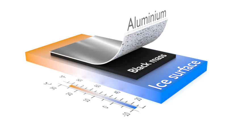
The “ice-stripping” delamination technique was further improved and modified by using a cold plate, in this example, a repurposed ice cream maker (Figure S2). The method exploits the contrast between the strong chemical bonding of the ice within the electrode vs. the relatively weak bonding and adhesion of the electrode coating to the current collector. The delamination process is similar to that described above, pouring water-place coating-freeze coating-peeling coating. The temperature of the ice cream maker can reach − 8°C, which is sufficient for the delamination process, and the freezing time was reduced to 5 min because of the lower quantities of water used. The ice adhered to the cold surface. The foil was then stripped away from the electrode materials, giving the advantages of using an ice-cream maker to delaminate the same scraps as above: 1) reduction in the amount of water required for the same scrap delamination (0.1 mL/cm2 electrode; 2) reduced the processing time (freezing time); 3) more straightforward to handle; and 4) potential to be scale-up and industrialised.
This technique has been further improved by spraying water into the electrode before placing it onto the cold plate (Apply gentle pressure on the electrode and peel the Al current collector (Figure S3)). For the same electrode scrap, the amount of water and the freezing time are reduced to 0.02 mL/cm2 and 10s, respectively.
|
No.
|
Electrode
|
Binder
|
Porosity(%)
|
Coating thickness (um)
|
Contact Angle (o)
|
|
1
|
PW
|
CMC/SBR
|
25±2
|
80±3
|
70.74
|
|
2
|
HC
|
CMC/SBR
|
35±2
|
50±1
|
42.85
|
|
3
|
PW
|
PVDF
|
30±2
|
80±3
|
73.01
|
|
4
|
NaTMO
|
PVDF
|
35±1
|
75±1
|
50.36
|
|
5
|
EoL Graphite
|
PVDF
|
28±1
|
75±1
|
25.86
|
|
6
|
LTMO
|
PVDF
|
35±1
|
70±1
|
75.85
|
The success of the method in allowing efficient delamination is facilitated by the fact that water can penetrate the electrode, and when water freezes into ice, water molecules become arranged into an organized 3D network, which creates more hydrogen bonds between ice and particles surface and a strong bonding network in the porous electrode as illustrated in Fig. 2a. Furthermore, the expanded volume from water to ice (nearly 9%) creates extra pressure within particles.
To confirm this, adhesion measurements were carried out with tape-peeling at room temperature and ice-stripping at -5oC. The adhesion forces were recorded when the whole black mass was peeled/stripped off from the current collector. For ice-stripping, the substrate was cooled to ~ -5oC before the test. Figure 2b-1 shows the distance between the electrode and cold substrate, temperature vs. time during the measurement. When the wetted electrode disc (d = 8mm) surface was in contact with the cold surface, the substrate temperature increased and became stable in 5 seconds, indicating successful heat transfer and resulting in the water in the electrode being frozen. The electrode was then stripped off after a few seconds to measure the adhesion between the black mass and Al foil. With increasing distance, the pull-off force was sharply increased till the black mass delaminated from the current collector (Fig. <link rid="fig2">2</link>b-2). During the ice-stripping process, the water penetrates the porous electrode, providing a stronger cohesive bond than the electrode's adhesive bond to the current collector. This results in the porous electrode components remaining on the cold surface after the current collector is stripped off. To further test the versatility of this delamination method, several different lithium and sodium electrodes from scrap or end-of-life, Prussian White (PW)-CMC/SBR, Hard Carbon (HC)-CMC/SBR, PW-PVDF, Sodium transition metal layered oxide (NaTMO)-PVDF, Lithium transition metal layered oxide (LTMO)-PVDF and Graphite-PVDF were also tested. The peel-off forces at room temperature and at -5oC were compared, as illustrated in Figure S4 and Fig. 2c. The force was reduced after the electrodes were frozen in most of the cases due to the stronger cohesive bond within the black mass from frozen water. However, there are exceptions, such as HC-CMC/SBR and LTMO-PVDF, where the pull-off force increased after freezing. The electrodes' porosity, thickness and contact angles were recorded as listed in Table 1 to understand the correlations. However, more coatings are required to obtain statistical results.
As a full-cell case study, the ice stripping delamination process was evaluated for a PW-HC A7 end-of-life Na-ion pouch cell. The cell was stabilised and opened, and the electrodes were removed before washing in IPA and then drying, as shown in Figure S5. The effect of the ultrasound-assisted delamination process (hammer (ball) milling) on the efficiency and the impact on the recovered materials was investigated and compared with the ice-stripping process. For the former, multiple steps, electrode resize, ultrasound-assisted milling delamination, current collector removal and binder removal, were processed as presented in Fig. 3. Moreover, some steps were required to be repeated a few times to maximize the delamination efficiency in this case. On the other hand, the ice-stripping process was straightforward. The compound separation efficiency of the coating is calculated using the equation below.
$$CSEcoating=\frac{mass of separated coating}{initial mass of coating}$$
If we take the HC-CMC/SBR coating as an example. Only 53% separation efficiency was achieved through ultrasound-assisted ball-milling delamination, whereas the ice-stripping technique can achieve a separation efficiency as high as 96% (Fig. 3). The coating separation efficiency via the ice-stripping method was also calculated with several other electrodes extracted from commercial cells, Calb (LFP), Thunder Sky (LCO), UKBIC (NMC) and Nissan (NMCA), and presented in Fig. 3b. High recovery yields were obtained at 98%, 100%, 93% and 95%, respectively. The delamination efficiency of thick electrodes can be improved by increasing the wetting time with more water. Porosity is considered a key factor as it allows water to penetrate the pores and freeze when the temperature drops. The electrode porosity of the commercial electrodes was all in the range of 25–35% (Fig. 3b), which the results show is sufficient to allow delamination of all the electrodes examined, illustrating the versatility of this technique.
The reclaimed PW and HC materials were then characterised to examine any changes in morphology and crystal structures (Fig. 4).
After delamination of the PW cathode and HC anode, the black masses were washed and centrifuged several times with water to remove the binders. The final reclaimed PW and HC power were dried at 120°C overnight. The XRD pattern of reclaimed PW shows cell symmetry change compared to the pristine PW, as shown in Fig. 4a. In line with this, the EDS results show that the average value of the Na/Fe ratio in the reclaimed PW power is lower at ~ 0.33, indicating Na loss from battery use and during/after the delamination process. Thus, the reclaimed PW powder is the lower Na content cubic phase rather than the as-received monoclinic phase. The HC reclamation is much simpler as the presence of water has less of an effect on the structure of HC, as shown in Fig. 4b. Figures 4c and 4d display the morphology of the PW coating from end-of-life cells before delamination and pristine PW powder. Figures 4e and 4f show the morphologies of the reclaimed PW powder via ultrasound-assisted ball-milling and ice-stripping techniques. The ice-stripping technique maintains PW's morphology and particle size, which is beneficial for subsequent direct recycling processes. Some unevenly distributed white stains were observed on the HC anode after drying, likely from Na plating during cell operation and SEI components after exposure to air during disassembly and washing processes. Nevertheless, after ice-stripping, the reclaimed HC powder maintained both the particle size and morphology.
The morphologies of the recycled Al current collectors were also studied, and the difference between ball-milling and ice-stripping delamination techniques was compared, as shown in Figure S6. Micro-wrinkles were observed on the Al surface after ball-milling, as shown in Figure S6a, which came from the zirconium balls, causing damage during milling. In addition, some un-delaminated PW powders were observed in some areas on the Al current collector (Figure S6b). These observations indicate that insufficient delamination was achieved from the ball-milling procedure. The damaged Al also reduces the chances of the current collector being directly re-used or re-manufactured for subsequent new battery production. Conversely, the Al current collector remained flat without wrinkles after ice-stripping at low temperatures (Figure S6c). After cold-plate delamination, the Al current collector surface remained flat, as shown in Figure S6d. This suggests that ice-stripping is more effective than ultrasound-assisted ball-milling as a delamination technique and offers more possibilities in current collector reuse.
The reclaimed PW (re-PW) and reclaimed HC (re-HC) were assessed for direct recycling possibilities and re-manufactured into an electrode with CMC/SBR binders. The pristine and recovered PW voltage profiles are compared. Galvanostatic charge and discharge profiles of re-PW showed less distinctive and much shorter plateaus, indicating lower Na contents in the reclaimed materials, consistent with the XRD results (Fig. 4a). This indicates that resodiation is required to recover performance.
The re-HC was also tested in a half cell in the voltage window of 0.01V-3.00V at a specific current of 10mA/g. The HC half-cell discharge profile consists of two distinct phases, a sloping region at high voltage and a plateau at low voltage 0-0.1V, corresponding to the absorption-intercalation mechanism28–30. The initial reversible capacity of re-HC is 245.5 mAh/g compared to 291.1 mAh/g achieved in pristine HC half-cell, as observed in Fig. 5b. The capacity deviation and cycling stability presented in Fig. 5c are likely due to the unwashed impurities in the reclaimed HC. The re-HC anode was also tested in a full cell configuration to avoid the challenges (high polarization) associated with testing vs. Na metal. The 1st charge-discharge profile of the PW/re-HC and PW/pristine HC are shown in Fig. 5d. The full cell assembled with re-HC gave similar profiles as the one with pristine HC, and the capacity was 121.8 and 128.6 mAh/g, respectively. However, the capacity decreased with time, and 70% of the capacity remained after 50 cycles for the PW/re-HC, as shown in Fig. 5e. This is likely due to residual binders and SEI layers in the re-HC powers. Further heat treatments are required to eliminate all the non-conductive binder polymers remaining in the reclaimed HC powers to restore the material to the equivalent of the original pristine material, which will be the subject of further studies. Nevertheless, the work illustrates that the ice stripping approach is an effective initial recovery step towards this direct recycling regeneration.
Sustainability and environmental impact
Due to the physical black mass delamination and the low operation temperature of -10 to 0oC ice-stripping method does not release any VOCs (volatile organic components) and environmentally harmful toxins that can be produced through high-temperature black-mass burning24, such as styrene, acrylates, unsaturated volatiles, or fluorinated products in the binder was fluoride-based. Moreover, due to technology flexibility and chemically non-destructive conditions, any black mass composition can be freeze-induced and delaminated from the current collector without chemical transformation or decomposition. Additionally, this procedure minimises the generation of solid or gaseous wastes. The carbon footprint for the ice-stripping process consists only of carbon emission due to energy consumption to cool the surface down to operating temperature. Measurement of electricity for the ice-stripping method was carried out using specialized meters that allow continuous recording from the beginning when the machine is turned on until the whole delamination process is completed. 0.025 kWh electricity consumption was recorded when 104g black mass was delaminated with the ice-stripping method. On the other hand, additional energy consumption, such as ethylene glycol (EG)12 manufacturing (0.36 kg CO2/kg31), need to be taken into consideration for the wet-chemical delamination process. Furthermore, the ice-stripping method does not require any harmful chemicals that can be found in pyrometallurgy and hydrometallurgy. The cooling agent varies from chemical cooling agents, closed-circuit Stirling engine or CO232,33. Such newer methods can reduce the environmental impact by more than four thousand times. It can reduce even further and reach zero carbon emission when taking advantage of the winter season in some Northern countries, where the temperature naturally drops to sub-zero degrees Celsius for a minimum of three months.
The ice stripping process has been demonstrated at the electrode sheet level on a small scale. However, there is potential to scale this to a continuous process, which is particularly useful for scrap electrodes. The constant coating from the manufacturing of electrodes, if needed to be scrapped, could be fed through either 1) an ice stripping roller and the double-sided coatings delaminated simultaneously or 2) a cold belt to delaminate side-by-side. Stripping could also be considered before drying, as the water or solvent could freeze and be stripped away from the current collector before entering the drying zone. Examples are given in Fig. 6. This continuous process further improves the energy cost and is used to reclaim material which can be directly reused in the manufacturing process with very little further processing.