The design concept of large PE devices at high luminance
In principle, PE is proportional to KrEPh/e×EQE/V, where Kr is the luminous efficiency of the radiation, Eph is the average photon energy over the full spectral range, EQE is the external quantum efficiency and V is the applied voltage.[33] In theory, KrEPh/e is closely related to the spectra, and according to Macadam's limit, a narrowband spectrum is more favorable for a high PE.[34] Therefore, in order to obtain a high PE at high luminance, a narrowband emission, a high EQE and a low V should be achieved simultaneously. However, this is quite challenging. Although a high maximum EQE has been achieved by using phosphorescence and TADF emitters, the efficiency roll-off in EQE with increasing luminance has puzzled researchers for decades. And taking into account the energy and resistance losses that occur during electron-photon conversion with increasing luminance, the PE roll-off is always more severe than that of EQE. Albeit the complex underlying physics, excitons involved bimolecular annihilations have been accepted as the main reason for EQE roll-off, which is highly related with the exciton concentrations.[28] Though enlarging the recombination zone could partially alleviate this issue, the intrinsic slow microsecond-scale radiative decays of both phosphorescence and TADF emitters would also pile up excitons under high luminance. Using a TADF molecular as a sensitizer for a final fluorescent emitter, termed TADF-sensitized fluorescence (TSF), has believed to be an effective way in accelerating exciton consumptions due to the additional rapid Förster energy transfer (FET) from sensitizer to emitter.[35, 36] However, owing to the competition from the fast intersystem crossing (ISC) process of the TADF sensitizer, the energy transfer in TSF would be a multi-time processes and long-delayed electroluminescence (EL) decay tails have been experimentally observed in previous works.[37] Therefore, though being alleviated compared with TADF device, the EQE roll-off of TSF device is still unsatisfied.
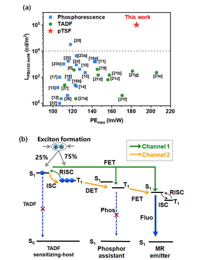
Fortunately, in our preliminary work, we proposed an advanced pTSF emission strategy, whereby a phosphor-assistant was introduced into TSF system.[38] Dual sensitization channels can be anticipated for pTSF, one being the FET process from singlet states of TADF sensitizing-host to that of the final emitter, another being the Dexter energy transfer (DET) from triplet states of TADF sensitizing-host to that of the phosphor and then to the singlet of the final emitter through a FET process. Different to multi-time FET processes in TSF system, the sensitization from phosphor to the final emitter is a one-way process, which thereafter greatly reduces the cycles numbers of the triplet ↔ singlet spin-flip transitions on TADF host induced by ISC process, thus eliminating the long EL decay tails in TSF system. As a consequence, pTSF devices could realize a 100% exciton utilization in a sub-microsecond-scale towards nearly free EQE roll-off. Nevertheless, towards a cutting-edge PE with alleviated efficiency roll-off, formidable challenges remain. To achieve an absolute PE value, not only a higher absolute EQE value is required, but also a narrowed electroluminescence spectrum bandwidth. Moreover, the wide-energy-gaps of TADF host and phosphor-assist required to guarantee efficiency energy transfer would inevitably cause energetic loss during the energy transfer to the low-energy-gap fluorophores. In terms of PE-roll-off, the adoption of wide-energy-gap host would also suffer from unbalanced and poor charge-carrier transport and inappropriate energy levels of the host that enlarge the interface barriers with the adjacent layers for charge injection, leading to the resistive loss reflected by the greatly enlarged operation voltage with increasing luminance, also causing severe PE roll-off.
With those in consideration, to unlock the full potential of PE performances on the basis of pTSF strategy, we constructed a narrowband pTSF emitting system consisting a TADF sensitizing-host, a phosphorescence-assistant and a MR emitter, as illustrated in Scheme 1b. The replacement of the final conventional fluorophore by a MR emitter could greatly enlarge the potential limitation of the absolute PE value because it could not only provide a narrowband spectrum for a high KrEPh/e value but also enlarge the absolute EQE value since the rigid planar structures of MR emitters prefer a horizontal emitting dipole moment orientation (EDO) to effectively enhance light outcoupling efficiency.[39] Besides, MR emitters are usually believed to be TADF molecules and thus possess the ability to harness triplet excitons themselves though being limited, thus favoring to block the exciton loss pathways through the dark triplet states faced by conventional fluorescence emitters. Least but not the last, owing to the small stokes shift of MR emitters, effectively transfer energy could be anticipated from TADF and phosphor sensitizers with Egs being energetically-close to that of MR emitters, reducing the energetic loss during this transfer originated from their different energy gaps.
Besides the adoption of MR emitters, the TADF sensitizing-host is also crucial to maximize the PE performance of pTSF device as it not only affects the sensitization process but also influences the resistive loss. One essential requirement for TADF sensitizing host is a fast RISC constant, which is usually the rate-determining steps in sensitization system and hence affect the sensitization efficiency. Besides, an anti-aggregation-caused quenching (anti-ACQ) character should also be realized to suppress the potential exciton annihilations on host considering the fact that under ultrahigh luminance, when the formation rate of excitons eventually exceeds their consumption rate, exciton saturation of dopants can be anticipated and thus excessive excitons on hosts.[28] In terms of reducing resistive loss, the TADF sensitizing host should simultaneously possess not only a good bipolar charge transporting ability but also suitable energy levels to match the adjacent transporting layers to reduce energy barrier. Interestingly, compared with conventional wide gap host with a large ΔEST, the donor-acceptor type TADF host with a small ΔEST would bear much smaller energy gap in the prerequisite of a same high triplet, which naturally favors orbital levels energetically-close to adjacent layers. Such characteristics of TADF hosts have already been adopted to reduce the operation voltages in phosphorescence devices.[20] Based on the above discussion, by proper molecular design of TADF sensitizing host, pTSF device with a MR emitter have the great chance to realize a high PE at high luminance.
The design and characterization of TADF sensitizing host
Taking all the above mentioned requirements, 5,7-bis(3-(4,6-diphenyl-1,3,5-triazin-2-yl)-[1,1'-biphenyl]-4-yl)-5,7-dihydroindolo[2,3-b]carbazole (DPT-IC) was constructed as a TADF-sensitizing host, of which the structure was provided in Fig. 1a. In this molecule, 5,7-dihydroindolo[2,3-b]carbazole (23bICz) and 2,4,6-triphenyl-1,3,5-triazine (TRZ) groups were chosen as the donor and acceptor segments, respectively, both of which possessed well-validated carrier transporting characters and moderate energy levels to match most transporting materials. Besides, this molecular adopts an orthro-linked acceptor-donor-acceptor (A-D-A) architecture aiming to, on one hand, to induce highly twisted molecular configuration so that the intermolecular interaction can be weakened to guarantee the anti-ACQ character, which can be further enhanced by the additional substitution of phenyl motif at the meta-position of triazine. On the other hand, the orthro-linkage would intrigue both through-space and through-bond charge transfer (TSCT and TBCT) transitions, which can be doubled by two equivalent acceptors. Those multiple transitions channels favor the generation of quasi-degenerate excited states to enhance the spin-orbital coupling (SOC) for a fast RISC, which can be demonstrated below.
To verify the rationality of molecular design, the electronic properties of DPT-IC were studied for which the ground-state optimization was performed by density functional theory (DFT) and excited-state electronic analysis by time-dependent DFT (TD-DFT) with a B3LYP/6–31(G)* using Gaussian program. Theoretical simulation showed a highly twisted stereochemical structure of DPT-IC with two TRZ groups being separately located at each site of 23bICz plane with torsion angles of 62.7o and 63.1o were recorded between the 23bICz plane and the linker-phenyl rings, respectively. Besides, dihedral angles between the triazine and linker-phenyl rings of 37.5° and 38.8°, respectively, were also observed. Figure 1b provides the frontier molecular orbital distributions of DPT-IC, showing a dominantly location of the highest occupied molecular orbital (HOMO) on 23bICz segment with part extending to the linker phenyl rings between donor and acceptor. As for the lowest unoccupied molecular orbital (LUMO), it volved equivalent distribution on both TRZ rings. Negligible orbital overlap between HOMO and LUMO favors a small energy difference (ΔEST) of 0.051 eV obtained from the theoretical predicted energy levels of the lowest singlet (2.562 eV) and triplet (2.511 eV). It is noteworthy that degenerate energy levels of singlet and triplet states were obtained with four pair degenerated singlets (S1-S4) and triplets (T1-T4) and the energy difference between T1 and S4 being merely 0.122 eV.
The origine of those degenerate energy levels, the existence of TSCT transition was theoretically analyzed firstly. The intramolecular face-to-face D/A motif endows close atom packing with distances in the range of 2.84–3.52 Å, favoring through-space electronic interactions. The reduced density gradient (RDG) analysis of DPT-IC was performed and the RDG isosurface map was provided in Figure 1c, revealing the presence of obvious intramolecular Van der Waals interaction as indicated by the green regions between ICZ donor and TRZ acceptor units. The RDG scatter diagrams also validated this enhanced weak interactions in the region that Sign (λ2)ρ is near 0 (red square). Those results clear validated the existence of TSCT transition in DPT-IC and the ratios of TBCT and TSCT transitions can be obtained using a reported method, being 32% and 68%, respectively.[40] Afterwards, the hole-particle analysis of those states was also conducted and provided in Fig. 1d. Interestingly, S1/T1 and S2/T2 showed clear characteristics of hybrid localized (LE) and CT excited states, being TBCT transitions, while S3/T3 and S4/T4 exhibited totally CT type orbital distributions, being TSCT transitions. This demonstrated our inspirations that the molecule with orthro-linked dual-acceptor could induce multiple CT transition channels for degenerate energy levels. The spin-orbital coupling matrix element (SOCME) values between those degenerate states were also calculated with Orca. The SOCME constants between T1 and S3, T2 and S4, T3 and S1 as well as T4 and S2 are all even over 0.3, which are remarkable for organic TADF based on only carbon, hydrogen and nitrogen atoms. And the SOC values between TBCT triplets and TSCT singlets or TBCT singlets and TSCT triplets are much larger than those of singlet and triplet states of TBCT or TSCT only. This is inconsistence with the El-sayed rules, that orbitals with different nature favors the spin-flip transitions. Though the underlying physics is debating, a second-order vibronic-coupling mechanism has been well recognized for RISC process in TADF molecular, whereby multiple states with different nature would mix with each other to mediate the RISC process. The degenerate energy levels of DPT-IC should therefore favor a fast RISC process theoretically.
The molecular synthesis procedure of DPT-IC was provided in Scheme S1 and a high yield of ~ 86% was obtained using a classical C-N coupling. The molecular structure was detailly characterized by H1 NMR, mass spectra and elemental analysis as provided in the Supporting Information (Figure S1 and S2). Its single crystal structure was also determined by X-ray diffraction as provide in Figure S3. As expected, a highly twisted structure was observed with the two TRZ segments being localized at the different sides of 23bICz group as predicted in the theoretical result. The torsion angles between the linker-phenyl rings and the 23bICz plane as well as the triazine rings were observed to be 58.16o and 72.58o as well as 26.65o and 26.28o, respectively. The twisted structure prevented the molecular interactions as expected. Analysis of thermal stability of DPT-IC was studied with thermogravimetric analysis (TGA) as depicted in Figure S4. A high degradation temperature (at which the weight loss achieves 5 wt%) of 408 ℃ is recorded, rationalizing the employment of DPT-IC as a host for evaporation process. The electrochemical properties of DPT-IC were studied by cyclic voltammetry (Figure S5), showing reversible reduction and qusi-reversible oxidation processes, suggesting both stable radical anions and cations. Moreover, moderate HOMO and LUMO energy levels of 2.7 eV and 5.8 eV were also obtained, which can well match the energy levels of the most adopted charge transporting materials. In addition to the intrinsic electronic properties of donor and acceptor moieties, those moderate energy levels also benefit from the small ΔEST of DPT-IC considering its high triplet levels.
Photophysical properties of DPT-IC and the doped films
Photophysical characterizations of DPT-IC were performed to further evaluate the rationality of molecular designing strategy. Ultraviolet-visible absorption (Abs), fluorescence (Fluo) and phosphorescence (Phos) spectra were measured in dilute toluene and given in Fig. 2a. From the Abs-spectrum, the absorption peaks at ~ 305 and ~ 362 nm can be assigned to the π-π* or n-π* transitions of 23bICz donor itself, in agreement with the results of 23bICz segment measured in toluene (Figure S6). As for the wide and weak absorption peak around 420 nm, it was believed to originate from the CT transition from donor to acceptor. Owing to the weak oscillator strength of TSCT transition, this CT absorption intensity is weakened, similar to other TADF molecular with TSCT transitions.[41] Besides, wide and structureless Fluo-spectrum was recorded with a maximum at 505 nm, in corresponding with the characteristics of a CT radiative transition. The phosphorescence also showed a wide emission spectrum, which suggests a main CT characteristic. Interestingly, the onset of Phos-spectrum is blue-shifted compared with that of the room-temperature Fluo-spectrum, which should be ascribed to the decrease of environmental polarity in frozen toluene matrix. Based on the onset energies of the Fluo- and Phos-spectra at 77 k, the corresponding S1 and T1 can be calculated to be 2.83 eV and 2.80 eV, respectively, together leading to a small ΔEST of 0.03 eV.
The photoluminescence quantum yield (PLQY) and the transient decay behaviors before and after degassing were further performed to evaluate the TADF performances of DPT-IC, as illustrated in Fig. 2b. DPT-IC solution exhibited a low PLQY of only 0.21 before degassing, while a high value of near unity after degassing. Meanwhile, the decay curve after degassing showed a classic double-exponential characteristic with the fitted prompt and delayed lifetimes (τPF and τDF) of 43.5 ns and 2.2 µs, respectively. Those behaviors clearly validate the TADF property of DPT-IC. Based on those results, the corresponding rates of the radiative decay (kr), RISC (kRISC) and ISC (kISC) can be calculated to be 4.8×10⁶ s− 1, 2.2×10⁶ s− 1 and 18.1×10⁶ s− 1, respectively. Though the high kRISC should benefit from the degenerate energy levels from our molecular design, a fast ISC process with nearly four-fold time larger was observed, which would compete with FET process in TSF channel as we discussed above. The anti-ACQ performance of DPT-IC was further evaluated by being dispersed into 9-(3-(9H-carbazol-9-yl) phenyl)-9H-3,9’-bicarbazole (mCPBP) films with a gradient doping concentration. As a result, with the doping concentration of DPT-IC increasing from 10 wt% to 100 wt% (pristine film), the corresponding PLQY values only showed slight decrease from 94–78% (Figure S7), suggesting significant anti-ACQ property as we anticipated.
To construct efficient pTSF film, the phosphor-assistant and the emitter should be finely chosen. In this work, bis[2-(2-pyridinyl-N)phenyl-C](acetylacetonato)iridium(III) [Ir(ppy)2(acac)] was chosen as the phosphor-assistant while 2',5',11',14'-tetra-tert-butyl-3a2',8a2'-diaza-15b'-boradispiro[fluorene-9,7'-diacenaphtho[1,2,3,4-defg:1',2',3',4',5'-pqrst]pentaphene-9',9''-fluoren]-1',3',3a1'(15c'),3b', 4',6',7a',7a1'(15b1'),8a',9a', 9a1'(12a'),11',12b',12b1'(15a'),14'-pentadecaene (tCzphB-FI) as the final MR emitter.[42] The related spectral information of involved molecules was depicted in Fig. 2c. Significant spectral overlap can be verified between DPT-IC emission and Ir(ppy)2acac/ tCzphB-FI absorption as well as between Ir(ppy)2acac emission and tCzphB-FI absorption. With the corresponding photophysical properties, the corresponding FET radii can be calculated to be 5.3 and 3.4 nm from DPT-IC to 2tCzphB-FI and Ir(ppy)2acac while 4.0 nm from Ir(ppy)2acac to 2tCzphB-FI, respectively, all suggesting highly-efficient energy transfer. What deserves to be pointed out is that such large FET radii are obtained under the circumstance that the emission peaks of both TADF host and phosphor-assistant are only slightly blue-shifted compared with that of the MR emitter. Therefore, the energy loss during the energy transfer process could be reduced on the maximum degree, favoring a high PE value. The reason should be attributed to the small stokes shift of the MR emitter. The doped film of DPT-IC: 10 wt% Ir(ppy)2acac: 1 wt% tCzphB-FI achieved a nearly unity PLQY with a small FWHM of merely 30 nm, validating the efficient energy transfer. Moreover, we also measured the angle dependent PL spectra of tCzphB-FI in the doped film to evaluate the horizontal EDO behavior of tCzphB-FI in the doped film and a high ratio of 92% was obtained. This could greatly enhance the light extraction of pTSF devices for a high EQE and finally a high PE.
Electroluminescence properties of devices.
OLED devices were constructed with structures of ITO/ HATCN (5 nm)/ NPB (30 nm)/ DCzPh (10 nm)/ EML (24 nm)/ 9Cz46m (10 nm)/ p-bpphen (30 nm)/ LiF (0.5 nm)/ Al (150 nm), in which HATCN was dipyrazino[2,3-f:2',3'-h]quinoxaline-2,3,6,7,10,11-hexacarbonitrile, NPB was N4,N4'-di(naphthalen-1-yl)-N4,N4'-diphenyl-[1,1'-biphenyl]-4,4'-diamine, DCzPh was 9,9'-diphenyl-9H,9'H-3,3'-bicarbazole, 9Cz46m was 4,6-bis(3-(9H-carbazol-9-yl)phenyl)pyrimidine and p-bpphen was 1,4-bis(2-phenyl-1,10-phenanthrolin-4-yl)benzene, respectively. The doped film of DPT-IC: 10 wt% Ir(ppy)2acac: 1 wt% tCzphB-FI was adopted as the emitting layer (EML). For comparison, TSF and TSP devices with EMLs of DPT-IC: 1 wt% tCzphB-FI and DPT-IC: 10 wt% Ir(ppy)2acac were fabricated, respectively. Figure 3a displays the corresponding energy levels of the device and the structures of the adopted molecules. Thanks to its D-A structure and the small ΔEST, the energy levels of PT-IC match well with the adjacent layers in prerequisite of a high triplet energy and thus generate small energy barriers for both hole and electron injection, favoring the direct charge recombination on TADF sensitizing host.
The electroluminescence (EL) spectra of those devices were recorded at 10,000 cd/m2 and provided in Fig. 3b. A wide green emission from Ir(ppy)2acac was observed for TSP device, showing an emission peak of 525 nm, a large FWHM of 62 nm and Commission Internationale de L'Eclairage (CIE) coordinates of (0.326, 0.631), respectively. Different to the TSP device, both TSF and pTSF devices exhibited dominant sharp green emission from 2tCzphB-FI with emission peak at 532 nm and a FWHM of only 30 nm. Nevertheless, the TSF device still showed a residual weak emission from DPT-IC while the pTSF totally showed 2tCzphB-FI emission, which suggests the more efficient energy transfer in pTSF device. A corresponding CIE coordinates of (0.289, 0.684) was obtained for pTSF device, displaying a better color purity compared with the other two devices. The luminance-voltage-current density characteristics of those three devices were provided in Fig. 3c and similar current density were observed, suggesting the similar charge recombination pathways in those three devices. Quite low operation voltages of 3.58 V at 10,000 cd/m2 and 5.15 V at 100,000 cd/m2 were observed for pTSF device, while those were 3.85 V and 5.82 V as well as 4.51 V and 6.76 V for TSF and TSP devices, respectively. Those low operation voltages for pTSF evidences the molecular design of DPT-IC in reducing resistive loss. Besides, a maximum luminance of up to 492,300 cd/m2 could be achieved for pTSF while only 129,000 cd/m2 and 209,100 cd/m2 for TSF and TSP devices. Given the similar charge transport on the host, the difference should mainly come from the relatively higher exciton utilization for more photons in pTSF device.
Figure 3d displays the EQE-brightness-PE characteristics of those devices. A rather high maximum EQE of 39.3% was obtained for pTSF device while only 17.8% and 25.7% for TSF and TSP devices, respectively. The high EQE of pTSF device originates not only high exciton utilization efficiency but also the preferential horizontal EDO of 2tCzphB-FI as demonstrated above. The angle-dependent EL intensity of pTSF device was also measured as illustrated in Figure S8, which basically followed the Lambertian distribution, suggesting that the device efficiency was not overestimated. Moreover, the pTSF device showed extremely low EQE roll-off, which remained 39.0% at 10,000 cd/m2 and 35.4% at 100,000 cd/m2. On the contrary, EQEs of TSF and TSP only remained 16.6% and 7.8% at 100,000 cd/m2, respectively. For practical applications, the roll-off in efficiency with increasing luminance can be quantified by the critical luminance L90%, that is the luminance at which the EQE has dropped to 90% of its maximum value. An impressive L90% of 97,100 cd/m2 can be obtained for pTSF device, validating the good performance of such strategy in alleviating EQE roll-off. Owing to the combination of low operation voltage, high EQE and narrowband spectrum, an unprecedently high maximum PE of 177.3 lm/W as obtained for pTSF device. More impressively, high PEs remained 145.1 lm/W at 10,000 cd/m2 and 92.5 lm/W even at 100,000 cd/m2 were observed. As comparison, only 15.1 lm/W and 33.4 lm/W were obtained for TSF and TSP devices at 100,000 cd/m2, respectively. The alleviated PE roll-off for pTSF device should be assigned to its not only the alleviated EQE roll-off but also the small energy loss and resistive loss with the increased luminance. The device operation stabilities of those devices were also testified under a constant current density with an initial luminance (L0) of 10,000 cd/m2. Figure 3e illustrated the relative luminance of those devices as a function of operation times. The pTSF device showed a LT90 of 114 h, significantly longer than the TSF and TSP devices, which only achieved a value of 45 h and 76 h, respectively. Those results greatly validated our inspiration that by wisely designing the TADF sensitizing host, an OLED based on the pTSF emission could unlock the full potential PE under high luminance and enhance device operation stability at the meantime.
To unveil the exciton consumption processes of those devices, the electroluminescence (EL) transient decay behaviors were monitored at the dominant emission peaks under the same voltage of 4V and the results were illustrated in Fig. 4a. For TSP device, a single-exponential curve was observed with a fitted decay lifetime of 0.897 µs, in agreement with the typical excited state lifetime of phosphorescence emission from Ir(ppy)2acac. For TSF device, after a short-lived but low ratio prompt part due to the energy transfer from the direct charge recombination generated TADF singlet to the MR emitter, a long-lived delayed tail with a main ratio was observed, which is even longer than TSP device and thus should account for its most severe efficiency roll-off. The delayed component should mainly originate from the singlet-to-triplet cycle on the TADF host induced by the ISC process as we discussed above. In terms of the pTSF devices, a clearly short-lived decay curve was observed compared with both TSF and TSP devices. Considering the high EQE of pTSF device, the influence of the nonradiative decay process could be ruled out and the short decay lifetime mainly arise from the accelerated exciton radiative consumption. The reasons of both efficiency roll-off and device degradation have been convincingly assigned to the exciton related annihilations, which leads to exciton loss and also molecular dissociation. The short-lived excitons in pTSF device could reduce the exciton concentrations under high luminance to decrease the possibility of exciton annihilations, thus explaining the alleviated efficiency roll-off and the prolonged device operation stability also.
To be more specific, a multi-exponential character was observed for the decay curve of the pTSF device, suggesting its multiple exciton radiative consumption channels. Initially, a fast decay component overlapping with the prompt part of the TSF device was observed, suggesting the direct TSF process. After that, the pTSF device exhibited a faster decay part compared with the TSF device, of which the reason is attributed to the additional sensitization process assisted by the phosphor as aforementioned. Those decay behaviors validated the existence of the multiple sensitization processes in the pTSF device. What needs to point out is that a long tail was also recorded for pTSF, which is even longer than TSP devices. The reason should be attributed to the slow TADF process of MR emitter itself. Even if the sensitization process could initially generate 100% S1 on the final emitter, the ISC process of MR molecular still leads to the formation of its T1 and then participate in the succedent RISC process, which, however, is dynamically slow (rate constant of usually ~ 103-104 s− 1). Fortunately, the ratio of the long tail is relatively low (< 10%) and the decay lifetime is still much shorter than TSF device, lowering down the influence on efficiency roll-off.
Furthermore, considering the fact that DPT-IC is a relatively better electron transporting compound rather than the hole one according to the single carrier devices (Figure S9), we optimized the EML structure by introducing 30 wt% DCzPh to construct a pTSF-1 device with an EML of DPT-IC: 30 wt% DCzPh: 10 wt% Ir(ppy)2acac:1 wt% 2tCzphB-FI, aiming to enhance hole transporting to further lower the driving voltage. As illustrated in Fig. 4b and Figure S10, an extremely low voltage of 4.25 V at 100,000 cd/m2 was recorded for pTSF-1, being 0.90 V lower than the above pTSF device, evidencing the small resistive loss with increasing luminance. To the best of our knowledge, this operation voltage represents the lowest one among the green OLEDs with common device structures in literature and it is even comparable with or better than the cutting-edge perovskite LEDs and polaritonic OLEDs, which are well-known for their low operation voltages.[30–32] This device also showed nearly roll-off-free EQE as illustrated in Figure S9b with a maximum value of 36.1%, which remained 33.3% at 100,000 cd/m2. Recently, Samuel and Zysman-Colman et al have summarized and analyzed the EQE roll-off of OLEDs using J90% as the yardstick and a high J90% of ~ 65 mA/cm2 was observed for the pTSF-1 device (Figure S9c). This value outperforms nearly all TADF and phosphorescent devices and is comparable with the best fluorescence ones but with nearly three-fold higher EQE value, evidencing the greatly alleviated roll-off in EQE together with high absolute values.[29] Combining with the high EQE and small resistive loss, a state-of-the-art PE with a maximum value of 187.7 lm/W was therefore obtained, which remained 158.0 lm/W and 103.3 lm/W at 10,000 cd/m2 and 100,000 cd/m2, respectively. More impressively, an extremely high LPE=100 lm/W of 114,330 cd/m2 was obtained, nearly one order of magnitude higher than previous works as illustrated in Scheme 1a. To the best of our knowledge, it is the first time that an OLED can keep a high PE over 100 lm/W at the exceptionally high luminance level of 100,000 cd/m2. Moreover, a long LT90 of 135 h was recorded for the pTSF-1 device at an initial luminance of 10,000 cd/m2 as depicted in Figure S9d. Using a regular degradation acceleration factor (n) of 1.75, the LT90 for pTSF device at an initial luminance of 1000 cd/m2 can be extrapolated to be 7,591 h, respectively, using an equation of LT90 (1,000 cd/m2) = LT90 (10,000 cd/m2)×(10,000 cd/m2/1,000 cd/m2)n, representing one of the longest lifetimes among OLEDs towards green Rec.2020 standard.[43]