3.1. Morphological and structural characterization of Fe3O4/E51/LY composite
The material structure of the sample can be inferred from the XRD data results. In the XRD pattern of Fig. 1a, the X-ray powder diffraction patterns of E51 and LY show a broad diffuse scattering peak near 20° and no peaks indicative of crystalline phases, indicating that the material exists in an amorphous form. The diffraction pattern of Fe3O4 hollow nanospheres has eight narrow peaks at 18.46°, 30.28°, 35.57°, 37.2°, 43.21°, 53.55°, 57.15°, and 62.68°, corresponding to (111), (220), (311), (222), (400), (422), (511), and (440) of Fe3O4 (JCPDS No. 19–0629) [15]. The diffraction peaks of Fe3O4/E51/LY composite are similar to those of Fe3O4 nanospheres, except that these peaks are slightly weaker.
FTIR analyses were conducted to confirm the coating of the magnetic particles with fluorescent material using resin. In the spectra of E51 and LY shown in Fig. 1b, the peaks at 2932 and 2860 cm− 1 can be attributed to the bending vibration of -CH. The peaks at 1600, 1535, and 1480 cm− 1 correspond to the stretching vibration of the benzene ring in the E51 and LY molecules. In the spectrum of E51, the characteristic peak of the epoxy group appears at 913 cm− 1 [19]. The characteristic absorption peak at 1070 cm− 1 is attributed to the stretching vibration of -SO3− in the LY molecule. The Fe-O group in Fe3O4 is located at 575 cm− 1. All these characteristic peaks are present in the spectral curves of the Fe3O4/E51/LY composite.
The SEM image of Fe3O4 particles synthesized by the solvothermal method shows that their morphology consists essentially of hollow spheres with a particle size of approximately 450 nm, as depicted in Fig. 2a. Figure 2b and 2c show the microscopic morphology of the LY pigments and E51 resin, respectively. Combined with XRD analysis, it is evident that both LY and E51 resin are in amorphous form. The Fe3O4/E51/LY composite was obtained by coating the surface of the nanospheres with the fluorescent pigment LY using resin. The particles were mixed and bound together by the resin with the fluorescent pigment, as shown in Fig. 2d. Elemental analysis of the microscopic surface of the material was performed using EDS-mapping. The distribution of the elements N, C, S, Na, O, and Fe in the composite is shown in Figs. 2f-2k, along with the mass percentage of these elements (Fig. 2l).
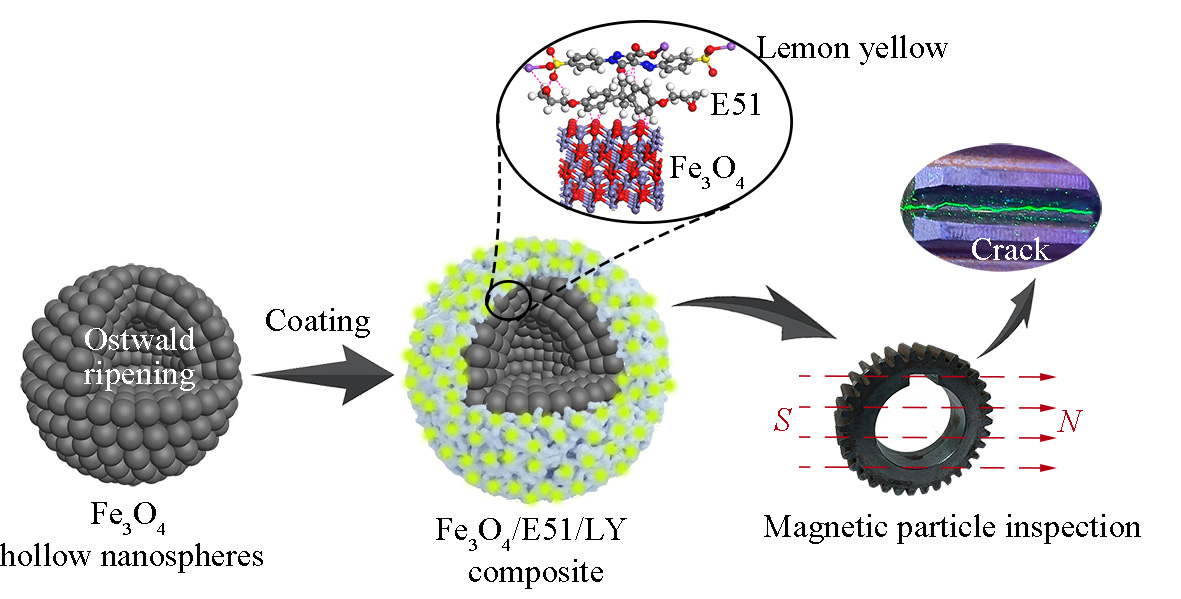
Fe3O4 nanospheres can be prepared by heating the reaction solution in a Teflon reactor at high temperature by the solvothermal method. According to the Ostwald ripening mechanism, at high temperature and pressure, the tiny particles inside the nanospheres dissolve, while Fe3O4 particles generated in the solution accumulate on the outer surface of the nanospheres. Due to the difference in surface energy between the inside and outside of the nanospheres, hollow nanospheres are gradually formed [20]. The E51 epoxy resin molecules contain various polar groups and reactive epoxy groups, which exhibit strong adsorption effects on the oxygen atoms on the surface of the nanospheres and on groups such as C = O and -SO3− in the LY fluorescent pigment molecules. The resin and amine curing agent undergo a crosslinking polymerization reaction to form Fe3O4/E51/LY composite blocks. After ball milling and crushing the blocks, most of the LY fluorescent pigments remain stably encapsulated on the surface of Fe3O4 nanospheres due to the resin’s adsorption. The encapsulation scheme is illustrated in Fig. 3.
3.2 Luminescence properties of Fe3O4/E51/LY composite
The results measured by fluorescence spectrometer, shown in Fig. 4, reveal the luminescence properties of LY fluorescent pigments and the Fe3O4/E51/LY composite. The LY fluorescent pigment exhibits a broad absorption peak between 325–500 nm (Fig. 4a). Under an excitation wavelength of 430 nm, LY emits a strong yellow-green fluorescence with a primary peak wavelength of 525 nm. The emission spectra of Fe3O4/E51/LY show a blue shift compared to that of LY, which is hypothesized to be caused by electrostatic interaction between the LY fluorescent pigment molecules and the E51 resin molecules. In the LY molecule, two benzene rings are linked by an azo bond -N = N- to form a conjugated structure, and the molecule contains numerous conjugated double bonds, allowing LY to effectively absorb photons and emit fluorescence [21].
The comparison of the luminescence of Fe3O4/E51/LY under visible and UV light is shown in the inset of Fig. 4b. The fluorescence intensity and fluorescence lifetime of the Fe3O4/E51/LY composite are reduced due to the quenching effect of the black Fe3O4 powder [22]. The decay curve data of the samples in Fig. 4c were fitted with a biexponential decay function, yielding average fluorescence lifetimes of 4.25 ns for LY and 3.10 ns for Fe3O4/E51/LY [15]. The fluorescence spectra of Fe3O4/E51/LY were further tested at different temperatures with an excitation wavelength of 430 nm, as shown in Fig. 4d. The intensity of the primary peak in the emission spectra gradually decreased when heated from room temperature to 150 ℃, indicating temperature-induced quenching of the luminescence. Despite the reduction, the material still exhibits significant fluorescence intensity at 150 ℃, demonstrating its suitability for use in complex temperature environments.
The phenomenon of luminescence observed in fluorescent materials is due to the transitions of electrons between different orbitals within their molecules. This results in a difference between the wavelengths of the excitation and emission peaks, known as the Stokes shift (Fig. 5a) [23]. Figure 5b shows the Jablonski energy level diagram of photoluminescence [24]. Upon absorption of UV light with an energy of hνA, the electrons in the molecule transfer from the ground state energy level (S0) to the unstable excited states (S1 or S2). Being in an unstable state, the electrons will return to the stable ground state. During the internal energy transfer process, the electrons transfer back to S1 by vibrational relaxation or radiative relaxation after absorbing light energy. From the S1 energy level, a non-radiative transition or emission of light with an energy of hνF occurs, which is called fluorescence. Another form of electron transition is intersystem crossing, where the transition from the triplet state to the ground state is accompanied by a non-radiative transition or emission of light with an energy of hνP, known as phosphorescence. The luminescence of the fluorescent pigment LY is classified as fluorescence. Figure 5c shows the CIE 1931 colorimetric diagram developed by the Commission Internationale de l'Éclairage. The curved contour line of the CIE chromaticity diagram represents the trajectory of all visible wavelengths [25]. The number along the line indicates the dominant wavelength of visible light. The color coordinates of the LY fluorescent pigment and the Fe3O4/E51/LY composite are (x = 0.25, y = 0.72) and (x = 0.19, y = 0.76), respectively.
3.3 Magnetic properties of Fe3O4/E51/LY
The magnetic properties of Fe3O4 magnetic nanospheres and Fe3O4/E51/LY magnetic luminescent composite were investigated using a VSM. The measured hysteresis loops are shown in Fig. 6a. The Fe3O4 hollow nanospheres demonstrated good paramagnetic properties and high saturation magnetization strength, with saturation magnetization values of 85.54 emu/g for Fe3O4 and 53.22 emu/g for Fe3O4/E51/LY. The remanence of the two was measured to be 8.64 emu/g and 2.16 emu/g, respectively, under a magnetic field of ± 2 T, and the coercivities were 77.55 Oe and 23.02 Oe, respectively. The magnetic suspension of the Fe3O4/E51/LY magnetic luminescent composite under UV light is shown in the inset. The magnetic luminescent particles in the suspension are attracted to the inner wall of the cuvette by a magnet, emitting a bright yellow-green color.
To gain a clearer understanding of the magnetic response properties of the Fe3O4/E51/LY magnetic luminescent composite, optical microscopy coupled with a double-pole electromagnet was used to observe the motion of Fe3O4/E51/LY particles under a uniform magnetic field. As shown in Fig. 6b and 6c, the Fe3O4/E51/LY particles are randomly distributed when the external magnetic field strength is zero, appearing yellow-green under UV light irradiation. When an external magnetic field is applied, the particles exhibit mutual attraction, agglomerating to form short chains. The direction of the chain length of the magnetic agglomerates aligns with the direction of the external magnetic field. As shown in Fig. 6d and 6e, when the uniform magnetic field strength is increased to 0.2 T, several short magnetic chains rapidly assemble to form a thick, long magnetic chain parallel to the magnetic field direction. Under UV light, a magnetic chain of approximately 500 µm in length with yellow-green fluorescence can be observed.
3.4 Magnetic particle inspection
The synthesized Fe3O4/E51/LY magnetic luminescent composite needs to be calibrated for concentration and tested for defect detection sensitivity prior to MPI. The well-dispersed Fe3O4/E51/LY magnetic suspension was poured into a centrifuge tube placed in a holder and left undisturbed for 1 hour in the absence of a magnetic field to allow the particles in the magnetic suspension to precipitate. As shown in Fig. 7a, the precipitated volume at the bottom of the centrifuge tube gradually increases. When the volume of precipitation is less than 0.1 mL, a certain amount of Fe3O4/E51/LY powder must be replenished to maintain the suspension’s effectiveness for MPI. This method is used to calibrate the concentration of the magnetic suspension after it has been used for flaw detection [26].
The sensitivity of the Fe3O4/E51/LY fluorescent magnetic composite was tested using a test piece shim, as shown in Fig. 7b. A 30 µm deep artificial defect was engraved on the surface of the test piece, which was then placed face down on an iron block. The calibrated magnetic suspension was sprayed on the back surface of the test piece while an alternating magnetic field was applied to the iron block for magnetization [27]. Due to magnetic flux leakage at the defects, the magnetic field intensity is higher at the defect edges. Under the magnetic field, the Fe3O4/E51/LY particles rapidly formed a yellow-green pattern on the back side of the test piece, indicating that the Fe3O4/E51/LY composite possesses good discrimination and sensitivity, accurately revealing the location of the defects.
Additionally, MPI experiments were conducted on a gear workpiece using the Fe3O4/E51/LY composite. The test bench model is illustrated in Fig. 8a. The experiments employed a method combining axial and circumferential magnetic fields. A current passed through the iron core connecting the electrodes on both sides, creating a circumferential magnetic field around it. This setup could detect axial surface defects on a rotary workpiece. Meanwhile, the ring solenoid generated a magnetic field parallel to the axial direction, allowing for the detection of surface defects perpendicular to the axial direction. A simple MPI test bench was constructed based on this model (Fig. 8b). The axial and circumferential magnetic fields were controlled by two AC power supplies on the left and right, respectively.
The steps of MPI included: preparation of the magnetic suspension, surface pretreatment of the workpiece, magnetization of the workpiece, spraying of the magnetic suspension, defect observation, demagnetization of the workpiece, and post-processing of the workpiece. Under UV light, yellow-green magnetic particle indications on the workpiece surface revealed surface defects. A camera was used to capture images of these defects for further analysis. As shown in Figs. 8c-8f, cracks between the tooth roots of the cast iron gear were clearly observed. These cracks, viewed under a fluorescence microscope, showed Fe3O4/E51/LY magnetic luminescent particles accumulating in the cracks due to magnetic flux leakage. The average width of the cracks between the tooth roots was about 50 µm. The Fe3O4/E51/LY magnetic luminescent composite effectively and accurately detected the defects on the gear surface.