The formation of zig-zags, chevrons, Y-junctions and line segments is demonstrated in thin films formed from cylindrical morphology Si-containing rod-coil diblock copolymers and triblock terpolymers under solvent annealing. Directed self-assembly of the block copolymers within trenches yields well-ordered cylindrical microdomains oriented either parallel or transverse to the sidewalls depending on the chemical functionalization of the sidewalls, and the location and structure of concentric bends in the cylinders is determined by the shape of the trenches. The innate etching contrast, the spontaneous sharp bends and junctions, and the range of demonstrated periodicity and line/space ratios make these conformationally asymmetric rod-coil polymers attractive for nanoscale pattern generation.
Article
WITHDRAWN: Bending Behaviors and Directed Self-assembly of Rod-Coil Block Copolymers
https://doi.org/10.21203/rs.3.rs-58565/v1
This work is licensed under a CC BY 4.0 License
Journal Publication
published 18 Feb, 2021
Read the published version in ACS Applied Materials & Interfaces →
Version 1
posted
You are reading this older preprint version
The full text of this preprint has been withdrawn by the authors while they make corrections to the work. Therefore, the authors do not wish this work to be cited as a reference. Questions should be directed to the corresponding author.
Editorial notes are used to provide important context regarding the topic of a preprint or to alert readers to potential issues concerning that preprint or a downstream publication associated with it. For more information on editorial notes, see our Editorial Policies.
conformational asymmetry
block copolymers
rod-coil
directed self-assembly
Block copolymers (BCPs) form a class of highly versatile materials, assembling into a variety of well-defined periodic nanostructures such as arrays of spheres, cylinders, lamellae and gyroids with periodicities typically in the range of 5−100 nm and a wide range of chemical compositions.1–3 BCP self-assembly provides a path towards the fabrication of complex heterogeneous structures with applications spanning energy harvesting and storage, filtration, functional surfaces, and nanoscale device fabrication.4–7 However, for applications in nanolithography, device-relevant features are required such as rectilinear geometries, tunable line/space ratios, and lines with bends and junctions.8–11 By taking advantage of traditional lithographic techniques to guide block copolymer self-assembly, directed self-assembly (DSA) has enabled the design of complex two- or three-dimensional nanopatterns governed by the interactions and the commensurability between a topographical or chemical template and the BCP.12–14 Most DSA has been based on coil-coil diblock copolymers or triblock copolymers or terpolymers, but the inclusion of diverse blocks such as in rod-coil BCPs has further extended the range of achievable microdomain morphologies and chemistries and raised interest in their application to nanolithography. Incorporation of a Si-containing block provides a good etch contrast and is particularly useful for pattern transfer.15
Conformationally-asymmetric block copolymers such as those containing rigid rods, polypeptides, polysaccharides, or polyhedral oligomers present self-assembled morphologies that differ qualitatively from those seen in coil-coil BCPs.16–20 The morphology is influenced by multiple parameters including the interaction parameter, molecular geometry, block fractions, block lengths and rigidity and the tendency of the rigid block to crystallize, and is highly dependent on the annealing process18,21,22 leading to a diversity of stable and metastable phases, such as zigzag smectic C-like morphologies21,23 and highly asymmetric lamellar structures.24
We focus here on conformationally-asymmetrical rod-coil Si-containing diblock copolymers and triblock terpolymers comprising a polydimethylsiloxane (PDMS) coil block and a semi-rigid poly{2,5-bis[(4‐methoxyphenyl)‐oxycarbonyl]styrene} (PMPCS) block.25,26 PMPCS is a mesogen-jacketed liquid crystalline polymer27 adopting an extended-chain conformation in solution and a columnar nematic liquid crystalline phase when thermally annealed in bulk.27,28 The PDMS-b-PMPCS (or DM) has a high interaction parameter and can microphase separate under thermal or solvent vapor annealing, with the liquid crystal (LC) ordering playing a role in the kinetic pathway determining the final morphology.29,30 The presence of silicon imparts a high etch selectivity between the two blocks, and is converted to silicon oxide on etching in oxygen, simplifying pattern transfer and making PDMS-containing BCPs attractive for nanolithography applications.15,31,32 We have produced well-ordered in-plane cylindrical silica patterns from PDMS-b-PMPCS thin films by thermal annealing,29 and a variety of core-shell patterns from a PDMS-b-PS-b-PMPCS (or DSM) triblock terpolymer by solvent vapor annealing,26 and also have generated well-ordered lamellae with out-of-plane orientation through a two-step annealing method.30
In this article, we demonstrate grating patterns with spontaneous sharp bends and Y-junctions as well as a tunable periodicity and line/space ratio from a series of rod-coil DM and DSM BCPs. In our prior work, we noted the formation of cylindrical microdomains with sharp bends in a solvent-annealed DSM triblock terpolymer.26 Here we show that the formation of such structures is not limited to the DSM triblock terpolymer but occurs generally for the DM diblock copolymers. The bends take the form of chevrons, Y-junctions, or discontinuous line segments depending on the bend angle and the block fraction. Furthermore, the cylinders can be aligned within topographical features with the cylinder orientation depending on the surface functionalization of the template, and concentric bends can be guided, creating device-relevant patterns by DSA.
Figure 1a shows the chemical structures of the PDMS-b-PMPCS diblock copolymer and PDMS-b-PS-b-PMPCS triblock terpolymer, and Table 1 summarizes the properties of the materials used in this study including molecular weight (Mn), degree of polymerization N, polydispersity (PDI), volume fraction f, acetone:heptane A:H ratio used for solvent vapor annealing (SVA), and period L0 with D, M and S subscripts representing PDMS, PMPCS and PS respectively. Syntheses of the diblock copolymer and triblock terpolymer were described in our previous work.25,26 The molecular weight of the PDMS block Mn(D) was fixed while its volume fraction fD ranges from 33–11%. Figure 1b demonstrates the fabrication steps used to convert films of DM or DSM into in-plane SiOx line patterns on flat and patterned silicon substrates (See Supplementary Information). The surfaces of the substrates were chemically functionalized by a 3 nm PS brush layer or a 3 nm PDMS brush layer. According to the Hildebrand solubility parameters of the PDMS (δPDMS = 15.3 MP1/2), PS(δPS = 18.5 MP1/2) and PMPCS (δPMPCS = 20.7 MP1/2) 33−35 the solubility parameter of PS lies approximately midway between those of PMPCS and PDMS suggesting that the PS brush will not be strongly preferential to either block in the DM. In contrast, the PDMS brush is highly preferential to the PDMS block. BCP films with thickness 30–100 nm were subsequently spin-coated and solvent vapor annealed36,37 using an acetone/heptane mixture at room temperature. The BCP films were etched by a two-step reactive ion etching to leave behind oxidized PDMS patterns.
| Sample | ND:NM or ND:NS:NM | Mn(D) a (g/mol) | Mn(PMPCS) a (g/mol) | PDI b | fD a (%) | fM a (%) | SVA (A:H) | L0 c (nm) | Line/ space ratio |
|---|---|---|---|---|---|---|---|---|---|
| D4KM12K | 58:30 | 4,300 | 11,700 | 1.07 | 33 | 66 | 8:1 | 16.5 | 1.2:1 |
| D4KM17K | 58:44 | 4,300 | 17,500 | 1.07 | 25 | 75 | 8:1 | 18.7 | 1:1.2 |
| D4KM21K | 58:52 | 4,300 | 21,100 | 1.05 | 22 | 79 | 7:1 | 20.8 | 1:1.6 |
| D4KM34K | 58:85 | 4,300 | 34,300 | 1.05 | 15 | 85 | 4.5:1 | 24.8 | 1:3 |
| D4KS7KM40Kd | 58:70:100 | 4,300 | 40,500 | 1.07 | 11 | 73 | 5:1 | 30.9 | 1:4 |
| a Determined from 1H NMR results of the macroinitiator and the block copolymers. b Determined from GPC using linear polystyrene standards. cDetermined from SEM of etched films. fD is the volume fraction of PDMS and fM is the volume fraction of PMPCS. dIn ref. [24] this polymer was named D58S70M100 representing its degree of polymerization. | |||||||||
Line-space patterns with a wide range of fill factors
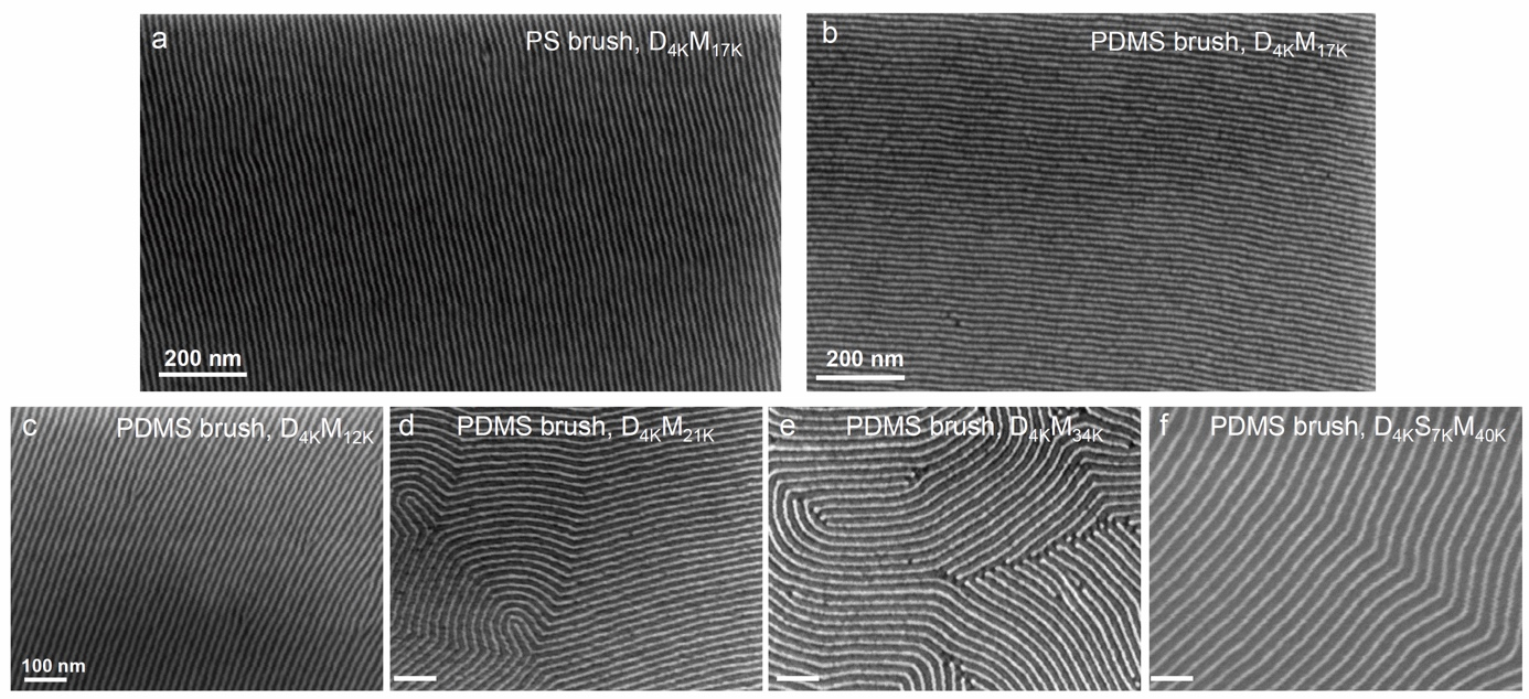
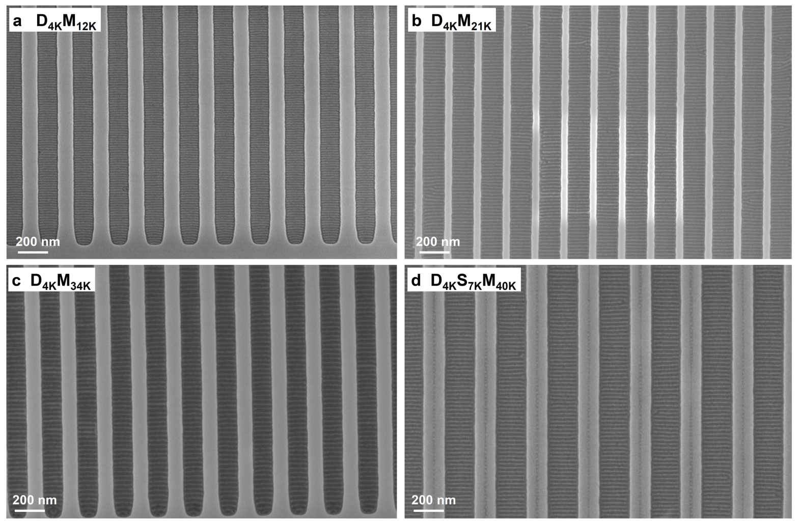
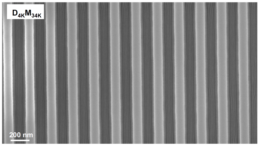
Solvent vapor annealing in mixed acetone/heptane vapors with appropriate composition produced in-plane cylindrical morphologies for all the BCPs. The etched top-view and cross-section SEM images of the films in Fig. 1c demonstrate highly ordered cylindrical PDMS microdomains on PS-functionalized substrates; similar results were produced on PDMS-functionalized substrates (Supplementary Information, Fig. S1). The preferential wetting of PDMS at the film/air surface (and at the film/substrate interface on PDMS-functionalized substrates) promotes the in-plane orientation. The acetone/heptane mixture ratio (A:H) that yielded well-ordered cylinders was 8:1 for D4KM12K, 7:1 for D4KM17K and D4KM21K, and 4.5:1 for D4KM34K, i.e. a greater amount of heptane was required as the PDMS volume fraction decreased, presumably because heptane selectively swells the PDMS to obtain an effective volume fraction consistent with forming a cylindrical morphology. Acetone constitutes the majority of the vapor, and the sum of the partial pressures of all solvent mixtures used here approached 30 kPa.26
Line-space patterns consisting of a monolayer of cylindrical microdomains were characterized from top-view SEM images of films (Fig. 1c). The DSM triblock terpolymer presents in-plane PDMS core-PS shell cylinders26 L0 is relatively small for these rod-coil BCPs compared with that of typical coil−coil block copolymers with similar molecular weight, due to the interdigitation of the rod block in the matrix,25,26 and the domain size of the PMPCS block is expected to scale almost linearly with the PMPCS molecular weight.21 The fill factor r varies between 0.20 and 0.55, covering a wide range that is advantageous for nanolithographic pattern generation. Cylindrical morphology BCPs typically form arrays with r ~ 0.5, though the range of r can be extended by annealing in selective solvents.38
Lines with spontaneous kinks and Y-junctions
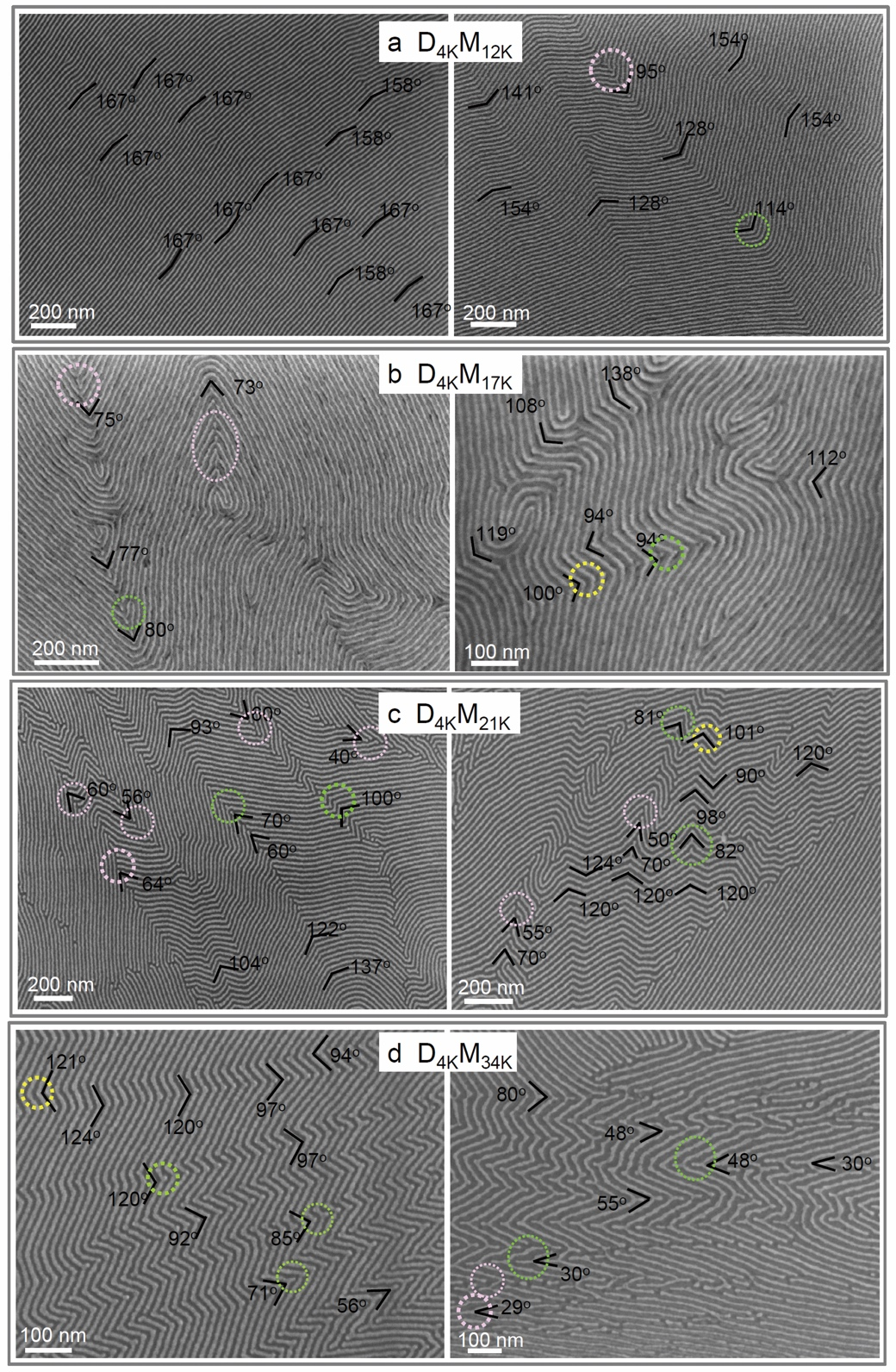
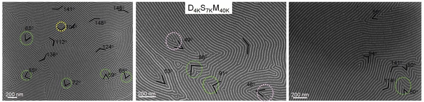
The most dramatic difference between the line patterns formed by the rod-coil BCPs and coil−coil BCPs is the spontaneous formation of zig-zag bends in the former, in contrast to the fingerprint patterns seen in the latter.39 The zig-zag morphology is shown in Fig. 2a for D4KM34K and in Fig. S2-3 for all of our BCPs. The cylinders formed sharp kinks or chevrons (V) and bends with a Y-junction structure or arrow (Y-bend),26 which are indicated by yellow and green circles, respectively. When the bending angle decreased to a small value, the bend is no longer continuous, and the cylinders form line segments (LS), indicated by light pink circles. The morphology therefore changes from chevrons to Y-bends to line segments as the bend angle became more acute.
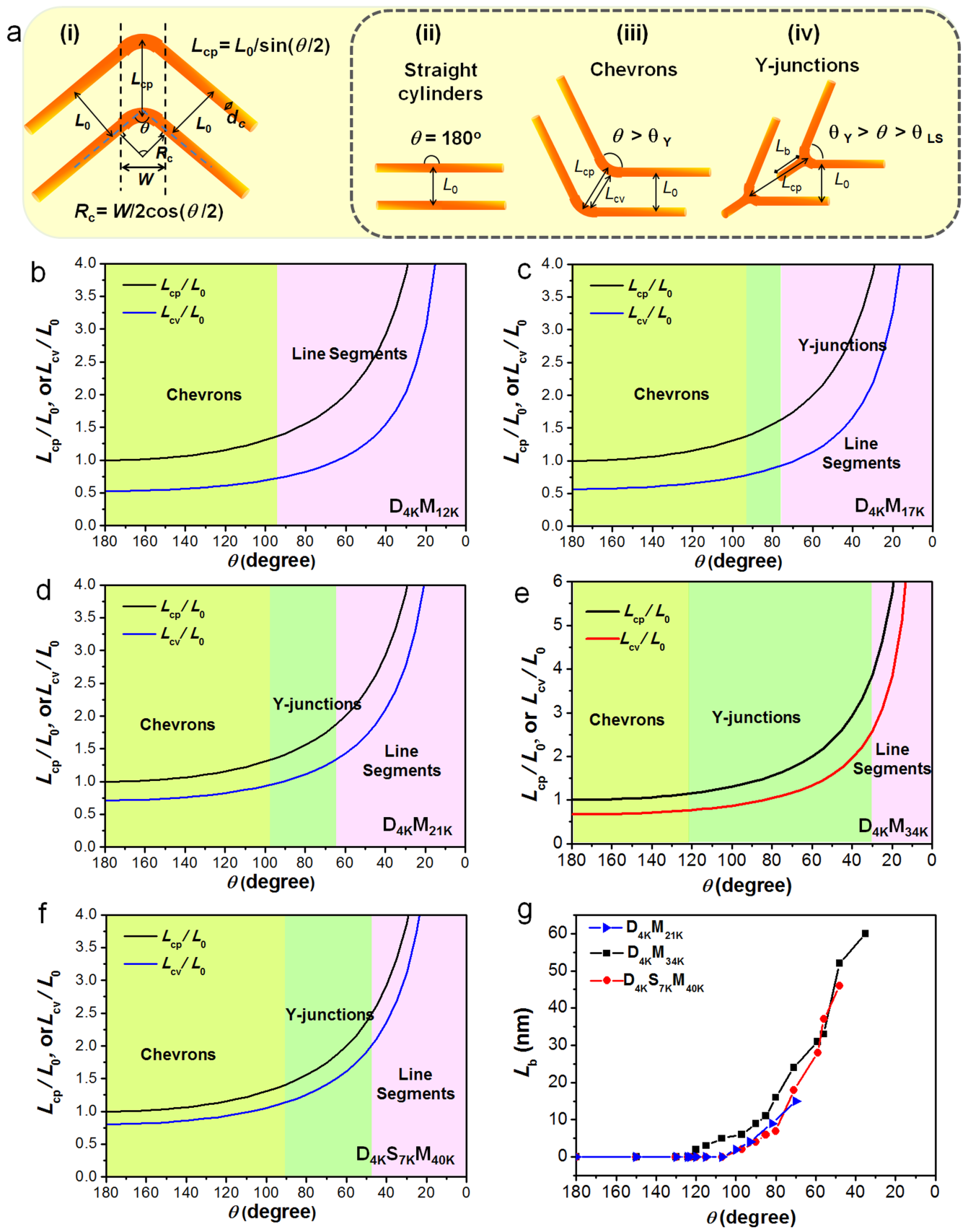
The critical bending angles at which the chevrons transition to Y-junctions (θY) and the Y junctions to line segments (θLS) are plotted as a function of volume fraction of PDMS (fSi) for all the block copolymers in Fig. 2b. A higher volume fraction of the rod-block, hence narrower PDMS cylinders, correlates with a wider range of existence of the Y-bends. The segment length at the Y-bends, Lb, (Fig. 2a inset and Fig. S4a) is plotted vs θ for D4KM21K, D4KM34K and D4KS7KM40K in Fig. S4g. The segment becomes longer as θ decreases because there is a larger spacing Lcp between the cylinders at the bend. Figure 2c shows the data normalized to L0, revealing that Lb/L0 increases with the volume fraction of PMPCS at fixed θ.
Zig-zag morphologies have been observed in several lamellar rod-coil BCPs16,20,21,23 and their energetics and internal structure have been examined theoretically.40–42 The zig-zag occurs in lamellar structures in which the rod block forms a liquid crystal smectic C arrangement, with the rods oriented at an angle to the intermaterial dividing surface (IMDS). The zig-zag represents a defect in which the tilt angle of the rods with respect to the IMDS is reversed. The tilting of the rods leads to a higher interface area but enables greater relaxation of the coil blocks, therefore it is stabilized by entropy of the coil block, and is promoted by annealing conditions that screen the block repulsion, e.g. the presence of a good solvent. The formation of zigzag lamellae is therefore process-dependent.21 In contrast, coil-coil BCPs lack the driving force provided by rod alignment, but sharp bends, kinks or zig-zags can be created by DSA43 and can occur at the grain boundaries between lamellae in bulk coil-coil BCPs.44–46 The Y-bend appears analogous to the omega structures observed in tilt boundaries of lamellar coil-coil BCPs.44,46 However, such omega or Y-bend structures have not been reported for cylindrical coil-coil BCPs, in which the cylinders at grain boundaries tend to form bends rather than junctions.47
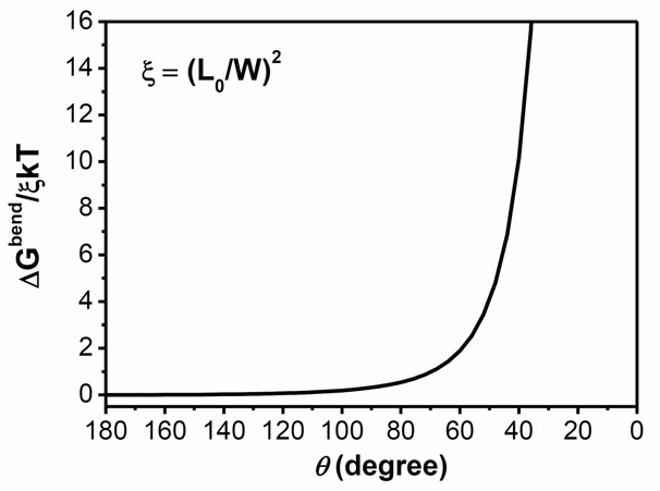
Our findings therefore extend the morphologies observed in cylindrical rod-coil BCPs to include both zig-zags and Y-junctions. The change in bend morphology with angle may be understood by considering both the origin of zig-zags in rod-coil BCPs and the chevron-to-omega transition in lamellar tilt boundaries. We first comment that the energetics of bending of microdomains in coil-coil BCPs is described in terms of the interfacial and chain stretching energies.48–50 The bending free energy per chain at a radius of curvature Rc is described in the Supplementary Information and Fig. S5, and scales with bending angle θ as:

where W is the bending boundary width as shown in Fig. 2b.46 This energy increases dramatically for sharp bends (i.e. low θ and low W), explaining why coil-coil BCPs favor the gradual bends seen in fingerprint patterns. Therefore, the formation of the sharp bends in the DM and DSM clearly indicates that an additional factor is stabilizing the sharp bends, namely the rod-rod interaction. It is significant that the zig-zag morphology was not seen in thermally-annealed cylindrical DM,29 which instead formed a fingerprint pattern. This supports the assumption that the solvent annealing plays a key role in reducing the interfacial energy so that the morphology is dominated by the rod-rod interactions. Thermal annealing at 200 oC causes a nematic orientation and more extended chain conformation for the PMPCS (L0,thermal anneal = 22 nm, L0,solvent anneal = 18.7 nm) in D4KM17K compared to the less rigid chain conformation and presumed locally smectic orientation formed during the solvent anneal. Under the solvent annealing, in which the PMPCS is swollen and the chains may form an interdigitated arrangement, the tilt of the rods could relieve the overcrowding, favoring bends and zig-zags.
The transition from chevron to Y-bend occurs with decreasingθ analogously to the chevron-to-omega transition in lamellar coil-coil BCPs: the additional line segment in the Y-bend reduces the stretching of the chains of the majority block required to fill the volume corresponding to increasing Lcp. The width W of the bent region (Fig. S4a) is larger for the chevron bends than for the Y-bends, e.g. in Fig. 2a, W = 54 nm for the chevron with θ = 137o, W = 26 nm at the transition from chevrons to Y-bends at θ = 120o, and W = 12 nm for the Y junction with θ = 90o. For small θ the Y-bend cannot form because there is insufficient volume to enclose the additional branched cylinder between the two straight sections of the cylinders, and the structure transitions to line segments; conformational asymmetry also favors the formation of line segments compared to bent continous microdomains, as observed in star copolymers.51 These considerations determine the angular range over which the Y-bend is stable.
Directed Self-Assembly of Bends
We now show how the locations and angles of the bends in the DM and DSM block copolymers can be determined by directed self-assembly using a template etched into the substrate. The templates were prepared by electron beam lithography on silicon substrates, then functionalized with a ∼3 nm thick PS or PDMS brush (see Supplementary Information). The sidewalls present a topographical guide and the polymer brushes provide a chemical guide for DSA. The as-cast film thicknesses were 30–50 nm, and during solvent vapor annealing the BCP on the mesas flowed into the trenches, which resulted in 50–100 nm thick films in the 100 nm deep trenches and at most a wetting layer of BCP on the mesas.
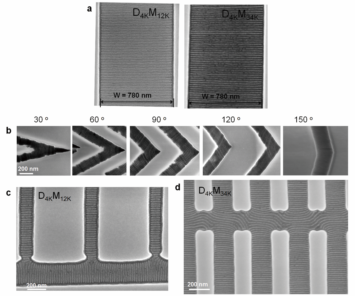
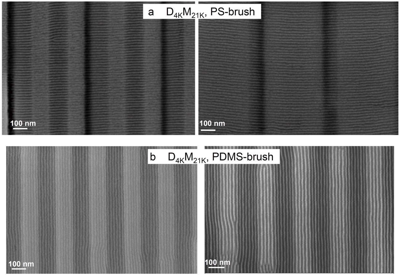
The solvent vapor annealed DM and DSM films present in-plane cylindrical morphologies within both PS and PDMS-coated templates, with orientation dominated by the brush. PS-brushed trenches led to cylinders oriented transverse to the trench shown in Fig. 3a for 120 nm wide trenches, and Fig. S6 for larger defect-free areas. The cylinder to cylinder distance is the same as that on the flat substrate. Transverse orientation is also produced for wide trenches (Fig. S7a) and in trenches with gradually changing width, Fig. 3b. In contrast, PDMS-brush functionalized trenches lead to parallel orientation of the cylindrical patterns of all the BCPs. D4KM12K, D4KM21K, D4KM34K and D4KS7KM40K present 7, 6, 4, and 3 cylinders in 120 nm wide trenches, respectively, Fig. 3c, and Fig. S8. This orientation occurred for narrow trenches, e.g. the D4KM34K presents a single cylinder in 30 nm wide trenches transitioning to two cylinders in 50 nm wide trenches (Fig. 3d). Figure 3e plots the number of transverse cylinders along a 625 nm long 120 nm wide PS-brushed trench, and the number of parallel cylinders in 120 wide PDMS-brushed trenches as function of BCP molecular weight.
The wetting behaviors of BCP films in PS-brush and PDMS-brush coated trenches are compared schematically in Fig. 3 f. In both cases, the top surfaces of the films form PDMS wetting layers because PDMS has a lower surface energy than PMPCS, implying that the morphological difference is a result of the wetting behaviors at the trench walls. PS brush coated templates preferentially adsorb the PS block of the DSM triblock terpolymer but are not strongly preferential to either block in the PDMS-b-PMPCS, because the solubility parameter of PS lies approximately midway between those of PMPCS and PDMS.33–35 The adsorption of both PMPCS and PDMS at the sidewalls for DM copolymers and the preferential adsorbtion of the middle block PS for DSM terpolymer favors the orientation of the PDMS cylinders perpendicular to the sidewalls, as schematically shown in Fig. 3 f. Metastable transverse orientations of cylinders have been observed due to capillary flow in other BCPs, evolving into a parallel orientation for longer annealing times,52 or by neutralizing the walls,53 but here the conformationally asymmetrical DM and DSM systems appear to form stable transverse cylinders.
In contrast, for the PDMS brush functionalized templates, the PDMS preferentially forms wetting layers at the top, bottom and sides of the film in the trench, and the cylinders are aligned parallel to the film surface and also to the trench walls. The transverse alignment in the PS-brush coated trenches and the parallel orientation in the PDMS-brush coated trenches was found in films with a range of thicknesses, and the polymer brush modified trenches can even guide the orientation and long range ordering of films much thicker than the trench depth, Fig. S9.
In our previous report of directed self-assembly of D4KM17K diblock copolymer in PS-brushed trenches by thermal annealing (200 ˚C, 72 hr),29 ladder morphologies (consisting of transverse cylinders joined to one parallel cylinder adjacent to each sidewall) as well as cylinders parallel to the sidewalls were formed depending on the film thickness and the groove and mesa width. In comparison, the transverse morphologies of the present study were produced consistently in DM and DSM films in PS-brushed trenches. The difference is attributed to the use of solvent annealing in the present study. The mobility of the rod-coil BCP under thermal annealing is lower than that produced by solvent annealing, and for the wider mesas not all the BCP flowed into the trenches during the thermal anneal. For solvent annealing the influence of mobility, wetting behavior and the swelling and LC configuration of the chains differ from the thermal anneal case and the ordering kinetics is faster.
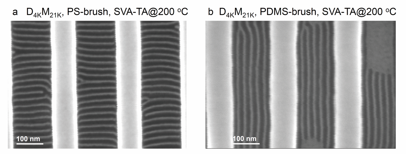
In prior work, a two-step anneal of D4KM21K consisting of solvent annealing followed by thermal annealing produced vertically-aligned lamellae in which the PMPCS exhibited a hexatic columnar nematic LC arrangement.30 The response of D4KM21K cylinders in templates to a subsequent thermal annealing process is shown in Fig. S10. The transverse or parallel orientation of the cylinders imparted by the PS or PDMS brush respectively during solvent annealing was preserved as they transitioned into lamellae, although some regions of in-plane lamellae were also observed. This process therefore provides a route to templating lamellae of different orientations within trenches via the surface chemistry. Lamellae are favored by larger molecular weight of the PMPCS as well as a more symmetric volume fraction.
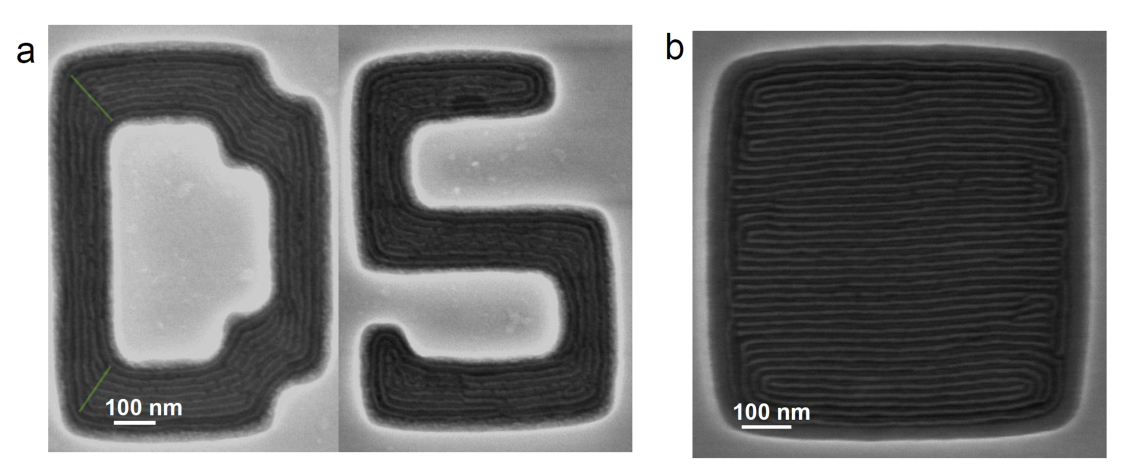
We now describe the templating of bends by directed self-assembly within V-shaped templates coated with a PS-brush. Figure 4a-b shows the transverse alignment of D4KM34K and D4KS7KM40K in right-angled trenches. Concentric bending occurs at the corners, and the bending angle of the PDMS cylinders θ is expected to be the supplementary angle of the bending angle of the trench (∠V). The D4KM34K and D4KS7KM40K form Y-junctions on flat substrates at a bending angle ∼ 90o, but in the trenches, wide chevrons are observed for both BCPs. The D4KM34K was also templated in 120 nm wide trenches patterned with ∠V = 30, 60, 90, 120 and 150o, Fig. S7b. The chevron bends display θ = 150, 120 and 90o for ∠V = 30, 60 and 90o respectively, but for ∠V = 120˚ and 150o, the cylinders are tilted with respect to the trench wall and Y-junctions are not observed. Figure 4c and Fig. S7c-d show the effect of other trench geometries. For PDMS-brush functionalized trenches, Fig. S11, the cylinders followed the sidewall contour and concentric bending was observed. These results show that in templated bends the chevrons are favored over Y-bends or line segments, and the angle at the bend is lowered by accomodating a tilt of the cylinders so that they are not perpendicular to the sidewalls. The control over transverse and parallel orientations may be useful in fabricating 3D multilayer structures relevant to microelectronic device layouts.
Summary
We demonstrate the formation of a series of grating patterns with scalable periodicity and line/space ratios from solvent annealed thin films of conformationally asymmetrical silicon-containing rod-coil block copolymers and terpolymers. Spontaneous bending leads to chevrons, Y-junctions and line segments, unlike the fingerprint patterns typically found in thin films of cylindrical or lamellar morphology BCPs. Directed self assembly within chemically functionalized topographical substrates produces a range of patterns with control over the cylinder orientation and bending. In particular, the surface chemistry of the patterned substrate yields in-plane cylinders either transverse or parallel to the sidewalls for a range of polymer compositions and film thicknesses. Furthermore, concentric bending of the cylinders occurs in trenches with angles. These results reveal a powerful platform for designing functional 3D nanostructures or device layouts by utilizing conformationally asymmetrical block copolymers.
Characteristics of the BCPs and thin film fabrication. Four different PDMS-b-PMPCS diblock copolymers were synthesized by atom transfer radical polymerization and a DSM triblock terpolymer was prepared by sequential atom transfer radical polymerization using the same monodisperse PDMS macroiniator (4300 g/mol, PDI = 1.02). 30–120 nm thick films were prepared by spin coating dilute solution of the BCP solution in toluene on the substrates. The concentration of the solution was 2∼5 wt% at various spin speeds. The film thickness was measured from the reflectance spectra of the BCP thin film within a wavelength range of 300 − 1000 nm by spectral reflectometry (FilMetrics F20-UV).
Solvent vapor annealing of the BCP thin films. Solvent vapor annealing was carried out with samples supported on a stage inside a solvent reservoir annealing system consisting of a closed chamber of volume 80 cm3 with 6 mL of liquid acetone:heptane mixture inside. The volumetric ratios of the acetone:heptane mixture in the chamber used to produce cylindrical cylinders for D4KM12K, D4KM17K, D4KM21K, D4KM34K and D4KS7KM40K were 8:1, 7:1, 7:1, 4.5:1, 5:1, respectively, corresponding to molar ratio 16:1, 14:1, 14:1, 9:1 and 10:1. The chamber had a loosely fitted lid that allowed the vapor to leak out slowly at room temperature, 23 ± 2 °C, with humidity 76%. The acetone:heptane mixture is a nonideal solution and the partial pressure of acetone is much higher than that of heptane. Based on experimental data for the binary liquid system of acetone and heptane, when the mole ratio of acetone in the mixed solvents was higher than 0.8, the total vapor pressure is estimated to approach the partial pressure of acetone at 298 K, ∼30.6 kPa.30,54
Patterned substrate fabrication A 300 nm thick positive ZEP 520A electron beam resist film was spin–coated onto a Si wafer with a 200 nm thermally grown oxide layer. The patterns were exposed with an Elionix EBL tool at a beam current of 10 nA. Then the exposed photoresist was developed with ZED N50 developer. A 4 min CF4/O2 plasma etching was used to transfer the patterns into the SiO2 layer. Finally, a piranha clean was conducted to remove the residual resist. The patterned substrates were then chemically functionalized with polymer brushes.
Chemical functionalization of substrates. The PS brush (hydroxyl terminated PS, 11.0 kg/mol, polydispersity index (PDI) = 1.10, Polymer Source, Inc.) and PDMS brush (hydroxyl terminated PDMS, 5.0 kg/mol, polydispersity index (PDI) = 1.07, Polymer Source, Inc.) were grafted to the surface of the flat and template substrates through the dehydration reaction between hydroxyl groups of the polymer chain and silanol groups of the silicon oxide during baking at 170 °C under vacuum (20 Torr) for 20 h. After thoroughly rinsing in toluene to remove unreacted excess polymer chains, a 3 nm PS brush layer and a 2 nm PDMS brush layer were obtained respectively. During annealing the BCP flows into the trenches. For example, in the template with trench width 120 nm and mesa width 80 nm, the initial 30 nm thick film leads to an estimated 50 nm thick film in the trenches after annealing.
Reactive ion etching of BCP films. A two-step RIE (Plasma-Therm 790) method consisting of a 50W CF4 plasma at 15 mTorr to remove the PDMS wetting layer on the surface and a 90W O2 plasma at 6 mTorr to selectively etch the PMPCS and PS matrix was used to convert the BCP patterns to oxidized in-plane PDMS cylinders. The etching time for D4KM12K BCP was 5 s of CF4 plus 5 s of O2, and that for D4KM12K BCP was 5 s of CF4 plus 8 s of O2, and that for D4KM34K and D4KS7KM40K is 3 s of CF4 plus 8 s of O2.
SEM imaging. Imaging of the etched samples was performed on a Zeiss Merlin SEM, with 2–5 keV accelerating voltage, ∼4 mm working distance and 100–150 pA. For cross-sectional imaging, microscopy was performed on the Zeiss Merlin similar to above with the sample held at an angle of 80o.
Acknowledgment.
Financial support from NSF DMR-1606911, the Semiconductor Research Corporation, the National Natural Science Foundation of China (Grants 51773124 and 51403132) and the Fundamental Research Funds for Central Universities are gratefully acknowledged. Shared experimental facilities of CMSE, an NSF MRSEC under award DMR-1419807, and the NanoStructures Laboratory were used.
- Bates, F. S. & Fredrickson, G. H. Block copolymers—designer soft materials. Phys. Today 52, 32–38 (1999).
- Mai, Y. & Eisenberg, A. Self-assembly of block copolymers. Chem. Soc. Rev. 41, 5969–5985 (2012).
- Bates, C. M. & Bates, F. S. 50th anniversary perspective: block polymers—pure potential. Macromolecules 50, 3–22 (2017).
- Kim, H.-C., Park, S.-M. & Hinsberg, W. D. Block copolymer based nanostructures: materials, processes, and applications to electronics. Chem. Rev. 110, 146–177 (2010).
- Jackson, E. A. & Hillmyer, M. A. Nanoporous membranes derived from block copolymers: from drug delivery to water filtration. ACS Nano 4, 3548–3553 (2010).
- Sai, H. et al. Hierarchical porous polymer scaffolds from block copolymers. Science 341, 530 (2013).
- Tang, C., Lennon, E. M., Fredrickson, G. H., Kramer, E. J. & Hawker, C. J. Evolution of block copolymer lithography to highly ordered square arrays. Science 322, 429 (2008).
- Stoykovich, M. P. et al. Directed self-assembly of block copolymers for nanolithography: fabrication of isolated features and essential integrated circuit geometries. ACS Nano 1, 168–175 (2007).
- Tavakkoli K. G, A. et al. Templating three-dimensional self-assembled structures in bilayer block copolymer films. Science 336, 1294 (2012).
- Doerk, G. S. et al. Enabling complex nanoscale pattern customization using directed self-assembly. Nat. Commun. 5, 5805 (2014).
- Majewski, P. W., Rahman, A., Black, C. T. & Yager, K. G. Arbitrary lattice symmetries via block copolymer nanomeshes. Nat. Commun. 6, 7448–7448 (2015).
- Cheng, J. Y., Mayes, A. M. & Ross, C. A. Nanostructure engineering by templated self-assembly of block copolymers. Nat. Mater. 3, 823–828 (2004).
- Segalman, R. A. Directing Self-Assembly Toward Perfection. Science 321, 919 (2008).
- Li, W. & Müller, M. Directed self-assembly of block copolymers by chemical or topographical guiding patterns: optimizing molecular architecture, thin-film properties, and kinetics. Prog. Polym. Sci. 54–55, 47–75 (2016).
- Lo, T.-Y., Krishnan, M. R., Lu, K.-Y. & Ho, R.-M. Silicon-containing block copolymers for lithographic applications. Prog. Polym. Sci. 77, 19–68 (2018).
- Chen, J. T., Thomas, E. L., Ober, C. K. & Mao, G. P. Self-assembled smectic phases in rod-coil block copolymers. Science 273, 343–346 (1996).
- Hoeben, F. J. M., Jonkheijm, P., Meijer, E. W. & Schenning, A. P. H. J. About Supramolecular assemblies of π-conjugated systems. Chem. Rev. 105, 1491–1546 (2005).
- Zhang, J., Chen, X.-F., Wei, H.-B. & Wan, X.-H. Tunable assembly of amphiphilic rod–coil block copolymers in solution. Chem. Soc. Rev. 42, 9127–9154 (2013).
- Ryu, J.-H. & Lee, M. in Liquid crystalline functional assemblies and their supramolecular structures (ed Takashi Kato), 63–98 (Springer Berlin Heidelberg, 2008).
- Schlaad, H., Smarsly, B. & Losik, M. The role of chain-length distribution in the formation of solid-state structures of polypeptide-based rod – coil block copolymers. Macromolecules 37, 2210–2214 (2004).
- Chen, J. T., Thomas, E. L., Ober, C. K. & Hwang, S. S. Zigzag morphology of a poly(styrene-b-hexyl isocyanate) rod-coil block copolymer. Macromolecules 28, 1688–1697 (1995).
- Osipov, M. A., Gorkunov, M. V., Berezkin, A. V., Antonov, A. A. & Kudryavtsev, Y. V. Molecular theory of the tilting transition and computer simulations of the tilted lamellar phase of rod–coil diblock copolymers. J. Chem. Phys. 152, 184906 (2020).
- Thomas, E. L., Chen, J. T., O'Rourke, M. J. E., Ober, C. K. & Mao, G. Influence of a liquid crystalline block on the microdomain structure of block copolymers. Macromol. Symp. 117, 241–256 (1997).
- Huang, M. et al. Highly asymmetric phase behaviors of polyhedral oligomeric silsesquioxane-based multiheaded giant surfactants. ACS Nano 12, 1868–1877 (2018).
- Shi, L.-Y., Zhou, Y., Fan, X.-H. & Shen, Z. Remarkably rich variety of nanostructures and order–order transitions in a rod–coil diblock copolymer. Macromolecules 46, 5308–5316 (2013).
- Shi, L.-Y. et al. Core–shell and zigzag nanostructures from a thin film silicon-containing conformationally asymmetric triblock terpolymer. ACS Macro Letters, 852–858 (2019).
- Chen, X.-F. et al. Mesogen-jacketed liquid crystalline polymers. Chem. Soc. Rev. 39, 3072–3101 (2010).
- Lyu, X. et al. Head–tail asymmetry as the determining factor in the formation of polymer cubosomes or hexasomes in a rod–coil amphiphilic block copolymer. Angew. Chem. Int. Ed. 57, 10132–10136 (2018).
- Shi, L.-Y. et al. Thin film self-assembly of a silicon-containing rod–coil liquid crystalline block copolymer. Macromolecules 52, 679–689 (2019).
- Shi, L.-Y. et al. Vertical lamellae formed by two-step annealing of a rod–coil liquid crystalline block copolymer thin film. ACS Nano 14, 4289–4297 (2020).
- Li, L. & Yokoyama, H. Nanoscale silica capsules ordered on a substrate: Oxidation of nanocellular thin films of poly(styrene-b-dimethylsiloxane). Angew. Chem. Int. Ed. 45, 6338–6341 (2006).
- Oh, J. et al. Universal perpendicular orientation of block copolymer microdomains using a filtered plasma. Nat. Commun. 10, 2912 (2019).
- Barton, A. F. M. Handbook of polymer-liquid interaction parameters and solubility parameters,1st edn, 125–147 (CRC Press, Florida, 1990).
- Shi, L.-Y., Shen, Z. & Fan, X.-H. Order – order transition in a rod – coil diblock copolymer induced by supercritical CO2. Macromolecules 44, 2900–2907 (2011).
- Gotrik, K. W. et al. Morphology control in block copolymer films using mixed solvent vapors. ACS Nano 6, 8052–8059 (2012).
- Jung, Y. S. & Ross, C. A. Solvent-vapor-induced tunability of self-assembled block copolymer patterns. Adv. Mater. 21, 2540–2545 (2009).
- Chavis, M. A., Smilgies, D.-M., Wiesner, U. B. & Ober, C. K. Widely tunable morphologies in block copolymer thin films through solvent vapor annealing using mixtures of selective solvents. Adv. Funct. Mater. 25, 3057–3065 (2015).
- Jeong, J. W., Park, W. I., Kim, M.-J., Ross, C. A. & Jung, Y. S. Highly tunable self-assembled nanostructures from a poly(2-vinylpyridine-b-dimethylsiloxane) block copolymer. Nano Letters 11, 4095–4101 (2011).
- Lane, A. P. et al. Directed Self-Assembly and Pattern Transfer of Five Nanometer Block Copolymer Lamellae. ACS Nano 11, 7656–7665 (2017).
- Li, W. & Gersappe, D. Self-assembly of rod – coil diblock copolymers. Macromolecules 34, 6783–6789 (2001).
- Pryamitsyn, V. & Ganesan, V. Self-assembly of rod–coil block copolymers. J. Chem. Phys. 120, 5824–5838 (2004).
- Gao, J., Song, W., Tang, P. & Yang, Y. Self-assembly of semiflexible block copolymers: 2D numerical implementation of self-consistent field theory. Soft Matter 7, 5208–5216 (2011).
- Ji, S. et al. Directed assembly of non-equilibrium ABA triblock copolymer morphologies on nanopatterned substrates. ACS Nano 6, 5440–5448 (2012).
- Matsen, M. W. Kink grain boundaries in a block copolymer lamellar phase. J. Chem. Phys. 107, 8110–8119 (1997).
- Gido, S. P. & Thomas, E. L. Lamellar diblock copolymer grain boundary morphology. 2. Scherk twist boundary energy calculations. Macromolecules 27, 849–861 (1994).
- Gido, S. P. & Thomas, E. L. Lamellar diblock copolymer grain boundary morphology. 4. Tilt boundaries. Macromolecules 27, 6137–6144 (1994).
- Jinnai, H., Yasuda, K. & Nishi, T. Three-dimensional observations of grain boundary morphologies in a cylinder-forming block copolymer. Macromol. Symp. 245–246, 170–174 (2006).
- Wang, Z. G. & Safran, S. A. Curvature elasticity of diblock copolymer monolayers. J. Chem. Phys. 94, 679–687 (1991).
- Wang, Z. G. Response and instabilities of the lamellar phase of diblock copolymers under uniaxial stress. J. Chem. Phys. 100, 2298–2309 (1994).
- Jung, Y. S., Jung, W. & Ross, C. A. Nanofabricated concentric ring structures by templated self-assembly of a diblock copolymer. Nano Lett. 8, 2975–2981 (2008).
- Yang, L., Hong, S., Gido, S. P., Velis, G. & Hadjichristidis, N. I5S miktoarm star block copolymers: packing constraints on morphology and discontinuous chevron tilt grain boundaries. Macromolecules 34, 9069–9073 (2001).
- Jung, Y. S. & Ross, C. A. Orientation-controlled self-assembled nanolithography using a polystyrene – polydimethylsiloxane block copolymer. Nano Lett. 7, 2046–2050 (2007).
- Bai, W., Gadelrab, K., Alexander-Katz, A. & Ross, C. A. Perpendicular block copolymer microdomains in high aspect ratio templates. Nano Lett. 15, 6901–6908 (2015).
- Maripuri, V. O. & Ratcliff, G. A. Measurement of isothermal vapor-liquid equilibriums for acetone-n-heptane mixtures using modified Gillespie still. J. Chem. Eng. Data 17, 366–369 (1972).
There is NO Competing Interest.
- bendingpaperSupportingInformationcr.docx
supporting information
- FigS1.png
SEM images of oxidized PDMS nanopatterns formed in D4KM17K films on PS-brush and PDMS-brush functionalized silicon substrates (a-b), and the oxidized PDMS patterns of D4KM12K, D4KM21K, D4KM34K and D4KS7KM40K films on PDMS brush functionalized silicon substrates (c-f).
- FigS2.png
SEM images of oxidized PDMS nanopatterns formed in D4KM12K (a), D4KM17K (b), D4KM21K (c) and D4KM34K (d) block copolymers thin films with the bending angle indicated. The yellow circles indicate the chevrons, the green circles indicate the Y-junctions and the light pink circles indicate the line segments, and the circles with bolder lines indicate the examples with critical bending angle around the bending morphology transition.
- FigS3.png
SEM images of oxidized PDMS nanopatterns formed in D4KS7KM40K terpolymer thin films with the bending angle indicated.
- FigS4.png
(a) Schematic illustrations of a model of bending morphology (i) and a comparison of straight cylinders, chevrons and Y-junctions (ii-iv). Phase diagrams of bending morphologies of D4KM12K (b), D4KM17K (c), D4KM21K (d), D4KM34K (e) and D4KS7KM40K (f) in the plots of Lcp/L0 and Lcv/L0 as function of . The length of segments (Lb) in the Y-junctions as a function of (g).
- FigS5.png
The plot of bending free energy per chain as function of , in which the constant is (L0/W)2 and W is the bending boundary width
- FigS6.png
Low magnification SEM images of transverse cylinders of D4KM12K (a), D4KM21K (b), D4KM34K (c) and D4KS7KM40K (d) block copolymers in 100 nm deep, 120 nm wide topographic trenches.
- FigS7.png
SEM images of transverse cylindrical patterns in 780 nm wide topographic trenches (a), in trenches with different bending angles (b), and in other geometrical patterned trenches (c-d). (Some breaks in the cylinders are attributed to overetching)
- FigS8.png
Low magnification SEM images of parallel cylinders of D4KM34K block copolymers in PDMS brush functionalized topographic trenches with width 120 nm.
- FigS9.png
SEM images of thick films of D4KM21K templated by PS brush and PDMS brush functionalized topographic trenches.
- FigS10.png
SEM images of D4KM21K vertical lamellae after two-step anneal in PS brush (a) and PDMS (b) brush functionalized topographic trenches. Some regions of in-plane lamellae are visible in (b).
- FigS11.png
The parallel orientation of cylinders of D4KM34K block copolymers in PDMS brush functionalized templates.