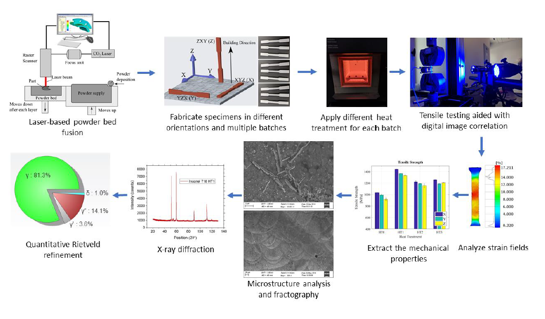
Mechanical Properties Test Results
The results of the tensile tests are summarized in Table 5, which lists Young's modulus, yield strength, tensile strength, ductility, and Poisson's ratio. These properties were calculated according to each specimens' individual dimensions to avoid variations caused by dimensional errors of the additively manufactured specimens. The influence of the proposed different solution annealing heat treatments on the mechanical properties of DMLS IN718 is better illustrated in Fig. 5. It shows the relationship between the samples' building orientation and the mechanical properties of as-built specimens (HT0), HT1, HT2, and HT3 heat-treated specimens. Each point showed in the figures is located using the average of the three repeated samples for each testing specimen listed in Table 1.
Table 4
Crystal information of the phases included in the quantitative XRD analysis
|
Phase
|
Space group
|
Lattice [A˚]
|
Atom
|
Location
|
Partial occupancy
|
Reference code
|
|
γ
|
Fm-3m
|
a = 3.598
|
Ni
Cr
Fe
|
(0, 0, 0)
(0, 0, 0)
(0, 0, 0)
|
0.50
0.30
0.20
|
10219-ICSD
|
|
γ'
|
Pm-3m
|
a = 3.57
|
Ni
Al
Ti
|
(0, 0.5, 0.5)
(0, 0, 0)
(0, 0, 0)
|
1.0
0.63
0.37
|
58039-ICSD
|
|
γ"
|
I4/mmm
|
a = 3.62
c = 7.41
|
Nb
Ni1
Ni2
|
(0, 0, 0)
(0, 0, 0.5)
(0, 0.5, 0.5)
|
1.0
1.0
1.0
|
105175-ICSD
|
|
δ
|
Pmmn
|
a = 4.25
b = 5.11
c = 4.54
|
Nb
Ni1
Ni2
|
(0.25, 1.75, 0.167)
(0.25, 0.25, 0.167)
(0.25, 0, 0.667)
|
1.0
1.0
1.0
|
COD-1522733
|
|
Laves
|
P63mmc
|
a = 4.796
c = 15.666
|
Nb
Fe1
Fe2
|
(0.333, 0.666, 0.563)
(0.17, 0.34, 0.25)
(0, 0, 0)
|
1.0
1.0
1.0
|
198050-ICSD
|
Table 5
Mechanical properties test results for DMLS samples of IN718 materials
|
Condition / orientation
|
Modulus [GPa]
|
Yield [MPa]
|
Tensile Strength [MPa]
|
Ductility [mm/mm]
|
Vxy
|
|
HT0 X-1
|
161.3
|
713.2
|
1039.2
|
39.01
|
0.31
|
|
HT0 X-2
|
138.5
|
696.0
|
1022.1
|
27.84
|
0.32
|
|
HT0 X-3
|
141.1
|
727.2
|
1040.1
|
28.96
|
0.30
|
|
HT0 Y-1
|
164.8
|
665.7
|
991.5
|
27.32
|
0.41
|
|
HT0 Y-2
|
128.7
|
654.5
|
976.0
|
27.79
|
0.43
|
|
HT0 Y-3
|
114.1
|
647.1
|
1005.5
|
27.05
|
0.39
|
|
HT0 Z-1
|
102.5
|
580.0
|
882.9
|
30.97
|
0.37
|
|
HT0 Z-2
|
83.1
|
615.6
|
930.4
|
33.63
|
0.36
|
|
HT0 Z-3
|
84.9
|
629.3
|
948.3
|
34.41
|
0.39
|
|
HT1 X-1
|
184.8
|
1208.3
|
1433.1
|
13.74
|
0.25
|
|
HT1 X-2
|
186.4
|
1214.8
|
1444.8
|
14.14
|
0.25
|
|
HT1 X-3
|
186.8
|
1216.4
|
1445.1
|
13.48
|
0.30
|
|
HT1 Y-1
|
179.0
|
1150.5
|
1361.9
|
9.07
|
0.27
|
|
HT1 Y-2
|
185.5
|
1162.5
|
1372.3
|
8.48
|
0.37
|
|
HT1 Y-3
|
182.5
|
1154.1
|
1369.0
|
8.86
|
0.34
|
|
HT1 Z-1
|
174.3
|
1114.5
|
1346.7
|
14.61
|
0.34
|
|
HT1 Z-2
|
169.1
|
1102.1
|
1319.2
|
14.53
|
0.37
|
|
HT1 Z-3
|
168.9
|
1102.0
|
1329.0
|
14.33
|
0.36
|
|
HT2 X-1
|
189.8
|
949.2
|
1203.0
|
18.08
|
0.31
|
|
HT2 X-2
|
196.1
|
945.2
|
1207.6
|
19.17
|
0.32
|
|
HT2 X-3
|
191.4
|
1014.8
|
1248.5
|
20.00
|
0.25
|
|
HT2 Y-1
|
187.6
|
940.6
|
1182.2
|
19.24
|
0.29
|
|
HT2 Y-2
|
193.6
|
960.0
|
1188.6
|
16.45
|
0.34
|
|
HT2 Y-3
|
187.2
|
979.3
|
1193.8
|
16.10
|
0.31
|
|
HT2 Z-1
|
174.6
|
908.7
|
1146.8
|
19.49
|
0.31
|
|
HT2 Z-2
|
174.4
|
908.5
|
1125.5
|
14.56
|
0.34
|
|
HT2 Z-3
|
180.3
|
980.4
|
1192.1
|
16.07
|
0.32
|
|
HT3 X-1
|
189.2
|
1060.3
|
1261.0
|
12.09
|
0.32
|
|
HT3 X-2
|
186.0
|
1055.8
|
1252.7
|
11.84
|
0.31
|
|
HT3 X-3
|
186.5
|
1050.2
|
1255.6
|
11.95
|
0.31
|
|
HT3 Y-1
|
179.0
|
965.7
|
1183.2
|
9.98
|
0.37
|
|
HT3 Y-2
|
173.1
|
956.4
|
1188.0
|
10.18
|
0.36
|
|
HT3 Y-3
|
175.5
|
959.9
|
1180.1
|
10.11
|
0.39
|
|
HT3 Z-1
|
170.9
|
1044.8
|
1213.7
|
11.40
|
0.40
|
|
HT3 Z-2
|
169.3
|
1035.2
|
1201.3
|
11.51
|
0.38
|
|
HT3 Z-3
|
171.2
|
1039.1
|
1211.4
|
11.55
|
0.36
|
Figure 5 shows that Young's modulus, the yield strength, the tensile strength, the ductility, and Poisson's ratio of the DMLS IN718 specimens are highly affected by the heat treatment scheme. Generally, all the mechanical properties increased after the solution annealing heat treatments and the aging except for the ductility. In Fig. 5(a) it can be seen that all the solution heat treatments resulted in a significant increase in Young's modulus for all orientations, especially the Z-built specimens, which were significantly lower in the as-built condition (HT0). HT1 resulted in the second-highest modulus for all orientations with HT2 being the highest. HT3 had the third-highest modulus. HT0 had the lowest modulus of elasticity with more than 40 GPa difference compared to the solution annealed specimens. In terms of solution annealed specimens, they all had lower variations in their Young's modulus among the different orientations compared to the as-built condition. It is noticed that the Z-built specimens had significantly lower modulus than the X and Y-built specimens with a difference of around 50 GPa, as well. In comparison, the difference in Young's modulus for the solution annealed specimens among different orientations was up to 15 GPa.
Results show that the yield strength increased significantly after the solution annealing heat treatments. HT1 showed the highest increase in yield strength with 500 MPa on average, followed by HT3, then HT2 with over 300 MPa increase compared to HT0, as can be seen in Fig. 5(b). Similarly, the tensile strength increased after the heat treatments, which can be illustrated in Fig. 5(c). The increase in the tensile strength value, however, is less than the one in the yield strength with around 400 MPa for HT1 and 160 MPa for HT2 and HT3. The difference among different orientations for HT0, HT1, HT3 was about 100 MPa for the tensile and yield strengths and about 50 MPa for HT2. It should be noted that while the difference between the X and Y-built specimens is much smaller compared to the difference between them and the Z-built specimens, the X-built specimens had higher stiffness and strength than Y-built specimens in every condition.
The ductility of the heat-treated specimens was significantly lower than the as-built specimens, as can be seen in Fig. 5(d). HT1 and HT3 had the lowest ductility with strains ranging between 10–15% at fracture, while HT0 had the maximum ductility with strains ranging between 27–32%. HT2 had the highest ductility among the solution annealed specimens with strains ranging between 16.5–19.0 % at fracture. Moreover, we can see that the Z-built specimens have the highest ductility in the ah-built condition and HT1 with the X-built specimens a close second and Y-built specimens showing the lowest ductility. In HT2 and HT3, the variation in the ductility of specimens fabricated in different orientations is reduced, and the X-built specimens having slightly higher ductility in both HT2 and HT3.
The influence of the heat treatments on Poisson's ratio vxy= - dεx/dεy is presented in Fig. 5(e). It can be seen that Poisson's ratio for the heat-treated specimens was generally higher than the as-built specimens. In addition, we can see that Poisson's ratio is generally lower for the X-built specimens and that the difference among the different orientations is minimum for HT2, which suggests improved isotropy.
Figure 6-Fig. 9 shows the strain fields of tensile specimens just before the fracture. From Fig. 6 we can see that as-built specimens suffered from high strains before failing. The effect of necking is clear with high strains in the necking area going up to 40% in addition to a large portion of the specimen enduring 20–25% strain, as can be seen from the histograms. HT1 specimens were able to hold significantly less strain before failing, and significantly less necking occurred before fracture, as can be seen from Fig. 7. The strain around the necking area dropped to less than 20% for both X and Z-built specimens and about 10% for the Y-built specimens, these results reflect the ductility results in Fig. 5(d). Also, the strain seems to be more uniformly distributed along the length of the specimens.
HT2 specimens seem to have recovered some of their ductility around 23–29%, and slight necking can be observed in Fig. 8, with more strain concentrated around the failure area. From Fig. 9 we can see that HT3 strain around the necking area had slightly higher values than HT1, but with less uniform strain distributed along the length of the specimens.
To evaluate the influence of the different solution annealing heat treatments on the anisotropy and repeatability of additively manufactured IN718, an anisotropy index (σA) is proposed. The anisotropy index (σA) is calculated by taking the standard deviation of the averaged property values for each orientation for a specific heat treatment which means it only calculates the variations of the averaged value for the X orientation, Y orientation, and Z orientation, which are the bar values shown in Fig. 5, without the error bars. The values for σA are summarized in Table 6. The σA values indicate that HT2 has the lowest variations in the mechanical properties of specimen fabricated in different orientations for all the mechanical properties except for Young’s modulus, where it was a close second after HT1, and for the ductility, where HT2 was a close second after HT3. A similar observation can be made by calculating the standard deviation for all specimens belonging to a specific heat treatment, without averaging them for each orientation before taking their standard deviation. This indicates that HT2 has the lowest anisotropy resulting from manufacturing the specimens in different orientations. In addition to that, HT2 has the highest reliability as the standard deviations for all of the specimens belonging to HT2 showed the lowest variations in their mechanical properties overall.
Table 6
Standard deviation of the resulting mechanical properties for different heat treatments
|
Heat Treatment
|
Young’s Modulus
|
Yield Strength
|
Tensile Strength
|
Ductility
|
Vxy
|
|
σA [GPa]
|
σA [MPa]
|
σA [MPa]
|
σA [mm/mm]
|
σA [dεx/dεy]
|
|
HT0
|
± 29.87
|
± 54.26
|
± 58.88
|
± 0.026
|
± 0.052
|
|
HT1
|
± 7.93
|
± 53.54
|
± 55.74
|
± 0.031
|
± 0.046
|
|
HT2
|
± 8.53
|
± 19.26
|
± 32.48
|
± 0.012
|
± 0.015
|
|
HT3
|
± 8.89
|
± 51.59
|
± 36.50
|
± 0.010
|
± 0.037
|
SEM Fractography
The fractured surfaces of the IN718 specimens are presented in Fig. 10-Fig. 13. From Fig. 10 we can see that the topography of as-built specimens is very prominent and rise high from the surface. Additionally, from the high magnification images in Fig. 10 (b,d), we can see clear topography. This indicates a ductile fracture mode. No clear distinction in the high magnification fractography can be discerned of the as-built condition of different orientations.
For the HT1 and HT2 heat-treated specimens, the fractured surfaces were mostly flat in the center but had high changes in topography at the edges, as can be seen in Fig. 11(a,c) and Fig. 12(a,c). However, the lips of the HT2 specimens are thicker, describing more ductile fracture than HT1 specimens. The topography observed in the high magnification images of HT1 is more similar to the ones observed in the as-built specimens than in HT2. The HT2 topography in the high magnification images shows wider pools and less deep than in the as-built condition specimens.
HT3 specimens' fractured surfaces are almost completely flat, even at the edges. In addition, the holes are more sparse, as can be seen in the high magnification images in Fig. 13(b,d), which could be caused by the much lower ductility shown by the HT3 specimens.
Microstructure Analysis
The microstructure of as-built specimens and heat-treated specimens is presented in Fig. 14-Fig. 18. We can see the effect of the specimens' building direction layer by layer in addition to the fusing of each layer along the laser's scan lines on the microstructure of the as-built specimens. In Fig. 14(a) the image shows a stack of layers from the bottom to the top, which indicates the building direction. We can also see the cross-section of the overlapping melt pools, which were scanned in a direction out of the plane. The needle-like microstructure can be observed in the X-built specimens. The needle-like dendritic microstructure seems to be aligned in some preferred orientations. This can be seen easier in Fig. 14(b) at 5kX magnification, where small spherical particles are aligned to create the needle-like patterns in the low magnification micrographs. The microstructure on the tensile force plane for the Y-built specimens was very similar to the microstructure shown in Fig. 14(a,b). However, the microstructure on the same plane for the Z building direction is completely different, as can be seen in Fig. 14(c, d). The top of scan lines can be seen since they are aligned in the plane for the Z-built specimens as opposed to the X and Y-built specimens, where we can only see the cross-sections of the scan lines and melting pools. No needle-like microstructure can be observed on the Z-built specimens, as shown in Fig. 14(c). Also, the high magnification micrograph of the Z-built specimens Fig. 14(d), shows that the particles are evenly distributed or growing in a direction normal to the imaging plane, thus eliminating the needle-like patterns. Figure 15 highlights the dendritic microstructure and the area it occupies. The X-orientation shows that more dendritic γ can be observed than in the Z-orientation, which clarifies differences in texture between the X and Z orientations.
The similarity in the mechanical properties between the X and Y-built specimens can be explained by the similarity in the microstructure on the planes normal to the tensile force, as observed in Fig. 14(a). On the other hand, the different microstructure patterns and texture developed in the Z-built specimens as shown in Fig. 14(c) explains the difference in Young's modulus and yield strength displayed by the Z-built specimens compared to the X and Y-built specimens. Texture is one of the most important factors influencing the lattice strain during loading [56].
HT1 specimens have shown similar microstructure in the low magnification images to the as-built (HT0) specimens. The faint melt pools in the X and Y-built specimens can be observed as shown in Fig. 16(a), and the top of the scan lines can be seen in Fig. 16(c). However, needle-like patterns are not present in any of the orientations. The high magnification micrographs show a completely different microstructure than the as-built condition. Plate-like particles, that were not observed in the as-built condition, can be seen from Fig. 16(b, d). The shape and size of these precipitates perfectly match the δ precipitates of IN718. These precipitates appear to be uniformly distributed with orientations of ~ ± 45˚ with respect to the building direction. which resulted in the high yield and tensile strengths of the HT1 specimens. The difference in the patterns in the low magnification images explains the different mechanical properties of X and Y-built specimens compared to the Z-built specimens.
Figure 17 shows the micrographs of HT2 specimens, as can be seen from the low magnification images. In Fig. 17(a, c), the melting pools and laser scan lines are completely replaced by a more homogenous microstructure with more defined grain and grain boundaries. This explains the more isotropic behavior of HT2 specimens. The high magnification micrographs Fig. 17(b, d) reveal the absence of precipitates even at the grain boundaries, which explains the lower tensile and yield strength of the HT2 specimens compared to the HT1 specimens.
HT3 micrographs show similar grains to HT2 specimens; however, with more defined grain boundaries due to the large plate-like precipitates present along the grain boundaries, as can be seen in Fig. 18. The high magnification images in panels b and d show a high abundance of these plate-like precipitates along the grain boundaries. The accumulation of δ precipitates at the grain boundaries of HT3 specimens explains the brittle behavior and the intergranular failure.
XRD Quantitative Analysis
The Rietveld refinement of the γ, γ', γ" and δ phases was completed successfully. However, the refinement failed to detect the presence of the Laves phase. Figure 19 shows the experimentally observed X-ray spectra, the Rietveld refinement calculated X-ray spectra, and the intensity difference between the observed and calculated spectra for the different heat treatment conditions of the DMLS IN718. The difference plots show that most of the fitting error is caused by the low diffraction angle peaks especially at 2θ = 51˚ which corresponds to the {111} of the matrix phase, which could be due to small changes in the lattice of the phases. The results of the quantitative analysis, in addition to the Rietveld profile fitting indices, are summarized in Table 7. The Rietveld refinement has shown that the as-built condition, HT0, has a minimal amount of precipitates, which included 6% for γ" and 3.6 for the δ phase. This explains the low tensile strength of HT0. The standard heat treatment has shown a significant amount of γ" in addition to 3.6% of γ' and the maximum amount of δ precipitates, which explains the increase in the tensile strength. HT2, on the other hand, showed the maximum volume fraction of γ' and small amounts of γ" and δ precipitates. This increase in γ' explains the improvement in the tensile strength over the as-built condition and due to small amounts of γ" and δ HT2 showed less degradation in its ductility compared to HT1. HT3 showed comparable amounts of precipitates for γ', γ", and δ phases. This makes HT3 the heat treatment with the highest amount of precipitates overall. This confirms the abundance of the plate-like δ found in the grain boundary of HT3. Therefore, HT3 showed an increase in yield strength over HT2. However, it suffered from low ductility comparable to HT1. This means that the grain boundary δ precipitates acted as stress concentration regions and led to an intergranular fracture. An additional heat treatment, labelled HT4, was explored where the dwelling time of the first step of the solution annealing heat treatment at 1270°C was increased to 10 minutes instead of 5 minutes with the rest of the heat treatment kept exactly as HT3. The result was a further increase in the δ phase to 18.6% and a decrease in the γ" precipitates to 8.6%. The γ' remained similar to HT3 with 11.2% instead of 10.3%. The specimens post-processed with this heat treatment performed very poorly and fractured before reaching the yield. The amount of δ precipitates was confirmed by thresholding the SEM micrographs and calculating the highlighted areas. Figure 20, shows the thresholded micrographs and the calculated areas occupied by the δ phase. This indicates that the morphology of the δ precipitates has a significant impact on the mechanical properties. The faction volume of the δ phase in HT1 is between HT3 and HT4 but the tensile strength and fracture behaviour were significantly different than both, which proves that the different morphology of the δ phase in HT1 is the reason and not just the fraction volume. Increasing the homogenization temperature and increased the growth rate of the δ phase at the grain boundaries. This indicates that depending on the heat treatment, different modes of strengthening will be involved. Furthermore, if the mode of failure is anticipated during the design process, then proper heat treatment can be chosen.
Table 7
Rietveld refinement results summary
|
Heat treatment
|
Volume fraction [%]
|
Rietveld Refinement agreement
|
|
γ
|
γ'
|
γ"
|
δ
|
R expected
|
R weighted
|
Goodness of fit
|
|
HT0
|
90.4
|
0.0
|
6.0
|
3.6
|
3.106
|
6.606
|
4.523
|
|
HT1
|
71.7
|
4.4
|
9.1
|
14.8
|
3.118
|
4.777
|
2.348
|
|
HT2
|
75.9
|
16.7
|
4.6
|
2.8
|
3.086
|
5.885
|
3.636
|
|
HT3
|
65.9
|
10.3
|
12.9
|
11.0
|
2.972
|
6.989
|
5.529
|