Characterization of catalysts.
The morphology and the lattice orientation of the catalysts were characterized by field emission scanning electron microscopy (FE-SEM), High-resolution transmission electron-microscopy (HR-TEM) and X-ray diffraction (XRD) techniques (Supplementary Figures 1-2). Upon self-doping, the anatase TiO2 nanotube arrays (TNTs) sample was found to be rich with surface OVs and Ti3+ defects as seen in our earlier work21. For the metal deposited composite catalysts, no characteristic peaks for both Pt and Au were seen due to high degree of dispersion or trace quantity of the metals12,22.
It was further characterized by aberration-corrected high-angle annular dark-field transmission electron microscopy (HAADF-STEM) to spot out the supported metal sites of the TNTs. As appeared in Fig. 1a, the bright spots seen on the TNTs are due to a severe aggregation of the Pt and Au that were nanoparticles larger than 2 nm in size, while the aglare bright spots (Fig. 1b) on the lattice surface of R-TNTs, were the atomically anchored Pt and Au, originated from the strong Z-contrast character23. As appeared in Fig. 1c of the energy dispersive X-ray spectroscopy (EDS) mapping, the atomic scale Pt and Au were evenly distributed throughout the support. While for the Pt-Au/TNTs, they obviously reflected the aggregated states (Supplementary Figure 3). As listed in Supplementary Table 1, the inductively coupled plasma optical emission spectrometer (ICP-OES) analysis of the composite catalysts, indicated that the mass contents of the Au and Pt in the range of 0.15% to 0.31%.
On account of the high surface free energy, the individual metal atoms are highly mobile and form aggregates during synthetic process10. While on the self-doped support of R-TNTs, they would normally get accommodated on the sites of defects, resulted in a decreased quantity of Ti3+ and OVs (Fig. 1d).
Interaction between metals and support
As seen in Fig. 2a, a prominent broad protuberance of light absorption, as a result of localized surface plasmon resonance (LSPR) effect of Au24, was observed for the both Au/TNTs and Pt-Au/TNTs composites in the range of 400~600 nm. While for the Au/R-TNTs and Pt-Au/R-TNTs, the absorption range was shifted upward featurelessly due to the defects but not the LSPR absorption. The LSPR effect of nano-scale Au that exhibits as the absorptive spectrum of near-infrared through the near-ultraviolet was well documented, which is mainly because of intraband transitions between the outermost electrons within the Au 6s1p hybridized atomic orbitals. As the size gets further decreased, the energy level of the hybridized orbitals would gradually get discrete and downward, and eventually merge with Ti atom of the support and lose the resonance feature25. Hence, corresponding the LSPR absorption gets gradually weakened and moved toward high energy region, eventually goes disappearing when the size is smaller than 2 nm26.
In the anatase phase of TiO2, the vibration modes of Ti-O bonding showed characteristic Raman signals (Supplementary Figure 4) at ~141 (Eg (1)), ~390 (B1g), ~515 (A1g) and ~634 (Eg(2)) cm-1, while introducing the OVs, the length of the bonding was altered, consequently a slight symmetric shift of 4 cm-1 was observed for the R-TNTs27. Furthermore, the Raman intensity of the Ti-O in Pt-Au/TNTs was significantly enhanced compared to that in TNTs. Under light irradiation, photo-induced electrons generated from nano-size Au, then migrated to TiO2 and inelastically collided with the electrons presented there, which boosted the vibration of Ti-O and in turn an enhancement of surface Raman scattering28. While for SAs modified semiconductor catalyst, the LSPR effect was no longer presented which could be a reason for the similar Raman features observed for both the Pt-Au/R-TNTs and R-TNTs as well.
As seen in the XPS 4f spectrum of the Pt (Fig. 4b) and Au (Fig. 4c), the absorption edge position was located between 0 to +4 valence for Ptn+ (n, 0~4) species and 0 to +1 valence for Auδ+ (δ, 0~1) species, respectively. Further, compared to Pt-Au/TNTs, an up-shift 0.34~0.36 eV of bonding energy (BE) was observed for both Pt and Au in the Pt-Au/R-TNTs composite, which was identical with that for monometal supported SACs in Pt/R-TNTs and Au/R-TNTs composites (Supplementary Figure 5). As the size decreased, the core-shell screening between the metal atoms would get weaken, which reflected the increase of core-level BE, namely a final-state effect of the species29. On the other hand, characteristic peaks of Ti4+, a negative shift at 0.61 eV in the Ti 2p spectra (Supplementary Figure 6) were observed upon a self-doping treatment. A positive shift of 0.2 eV in the Ti 2p peaks observed for the atomic Pt/Au anchored R-TNT. The bonding between the support and the atomic Pt/Au made the BE shift, which was a concrete evidence for the uniform anchoring of atomic Pt and Au on the support..
Moreover, the normalized L3-edge X-ray absorption near-edge spectroscopy (XANES) for Pt and Au was presented in Fig. 2d and Supplementary Figure 6, respectively. The observed higher intensity of Pt L3-edge white line compared to the Pt foil reference as well as a new prepeak (11530~11550 eV) appeared in advance for the SAs Pt-Au/R-TNTs, revealed that atomic Pt in the SAs Pt-Au/R-TNTs was positively charged. Further, the new prepeak should be attributed to the transition of hybridization between Pt 5d and O 2p orbitals30, therefore, the Pt species should exist as compounds. As far as the normalized Ti K-edge XANES (Fig. 2e), the three prepeaks (4960~4980 eV, inset of the Fig. 2e) observed against both R-TNTs and SAs Pt-Au/R-TNTs, reflected the higher intensity and non-centrosymmetric characteristics unlike for the perfect TiO2 by which the presence of defects near Ti atom was confirmed. Furthermore, the existence of three Ti–O shells (R = 1.12, 1.54, and 2.12 Å)31 was confirmed by the fourier transform extended X-ray absorption fine structure (FT-EXAFS) of Ti (Fig. 2f), wherein the length of those bonds for R-TNTs sample was found to be shortened due to the introduction of OVs32. Upon anchoring the Pt and Au, two of the shortened Ti-O bondings in the R-TNTs got resumed, the bond length even exceeded for perfect TiO2, however, since relative instability of the third Ti-O shell (R = 2.12 Å), of which bonding interaction might be substituted by the MSI, a total disappearance of signal was observed. The introduced metals could trap electrons from defects and make bonding with the uncoordinated defects form M-Ti-O or Ti-O-M, by which Ti-O underwent an elongation. It is very clear that the affinity of the defects towards atomic Pt/Au was very high, and the atoms initially located nearby the vacancy, were readily trapped by the defects with lone electron. More specifically, the 5d orbital of Pt caught the electrons from 3d orbital of Ti3+ via bridging O, while the 6s orbital of Au directly trapped a single electron from 3d orbital of Ti3+. The defects-associated atoms of both the metals, are largely covalent in nature and tend to form bonding of Pt-O and Au-Ti33,34. These results suggested that a uniform dispersion of single atomic scale Pt and Au on the surface of the defected TNTs support, and that reflected in the spectral analysis as unique characteristics.
Photocatalytic reduction of CO2 and photoelectric properties of the catalysts
To evaluate the performance of the fabricated catalyst composite on CO2 reduction, several control experiments were initially conducted, that included (i) treating the gaseous mixture of CO2 and H2O with the catalyst under dark condition; (ii) irradiating the gaseous mixture without catalyst; (iii) irradiation of the (i) but without H2O, and (iv) irradiation of the (i) but without CO2. No hydrocarbons were found to be formed in all the mentioned cases even at an extended reaction period of 3 hours, proving that the sources of carbon and proton were only from the input of CO2 and H2O, respectively.
The yields of photocatalytic CO2 reduction by using the SAs Pt-Au/R-TNTs, Pt-Au/TNTs, and R-TNTs composites under illumination, were shown in Fig. 3a-b and their corresponding products were listed out in Supplementary Table 1. As seen, the products viz. C2H6 and CH4 were formed by the SAs Pt-Au/R-TNTs composite catalyst and their maximum rate of generation were shown to be 28.8 and 360.0 µmol g-1 h-1, respectively, for which the corresponding AQYs were of 2.7 and 15.2 % (total value of 17.9%). The photocatalysis of 13CO2 isotope labeling further confirmed the reduction products, for which the signals (Fig. 3c) of the isotopic 13CH4 and 13C2H6 were seen at m/z=17 and 32, respectively, and their fragment ions were also observed at m/z = 15, 16, 30, and 3135,36.
A much higher photocatalytic activity towards CO2 reduction was observed with SAs Pt-Au/R-TNTs composite, for instance, it was 5.5 and 149 times higher than that of Pt-Au/TNTs and R-TNTs, respectively. Interestingly, the synergistic effect was found with a binary combinations of atomic Pt and Au, in which 2 times higher rate of CO2 reduction was seen compared with the monometallic system (SACs) of either Pt or Au (Supplementary Figure 8) at same quantity (wt. %) of the SAs metal. Also, the reaction of C-C coupling was favored by the SAs Au/R-TNTs thereby a formation of C2H6, which was not feasible with SAs Pt/R-TNTs.
Nevertheless, the evolution of hydrocarbon was getting decreased as the cycles increased and the activity of SAs Pt-Au/R-TNTs gradually decreased during the reaction (Supplementary Figure 9a). It has been reported that the salt intermediate products such as HCOO-, HCO3-, and CO32- get adsorbed preferably on the active sites, which possibly resulted in a deactivation of the photocatalyst37. The peaks displayed in the attenuated total reflectance Fourier transform infrared spectra (ATR-FTIR), were attributable to the bending vibrations of carbonate, stretching vibrations of O-H and C-H bonds of the intermediate species that existed after completion of the photocatalysis process, which could possibly block the active sites of the catalytic surface (Supplementary Figure 10). If this was the case, scouring the surface with deionized water should have restored the activity by recovering the active sites, but the restoring was only partial (Supplementary Figure 9b). The deactivation phenomenon might be originated from the sacrificial oxidation of the catalyst caused by photo-induced holes. To verify the self-oxidation step, a control experiment was conducted by replacing the water gas with 10 vol % mixture of CH3OH/H2O. Interestingly, the activity of the photocatalyst was retained with a higher durability for the hydrocarbons yield (Supplementary Figure 9c). The catalyst underwent deterioration by the self-oxidation, thereby a decelerated photo-reduction of CO2. During the process, -OH groups that terminated on the surface of TiO2, were oxidized into •OH, which could in turn oxidize the catalyst itself. However, by substituting CO32- with –OH, the durability and activity of the photocatalysis were high and stable for at least 4 runs (Fig. 3d) of the process. Because the CO32- would get oxidized into O2 but not the •OH, thus the self-oxidation of the catalyst was controlled38.
Excluding the slight shift of the energy band gap of the catalysts, the introduction of defects and loading of SAs had major impact of developing an integrally enhanced system for absorption of the light in the visible and near-infrared regions (Fig. 4a), as well as extended lifetime of the carriers. As seen in Fig. 4b, the decay kinetic analysis of the catalysts showed that the longest average fluorescence lifetime of 105.1 ns was from the SAs Pt-Au/R-TNTs, contrast to 55.3, 35.6, and 28.3 ns from the Pt-Au/TNTs, R-TNTs, and TNTs, respectively. And the finding was further substantiated by the steady state photoluminescence emission (PL) measurement and photocurrent studies. Upon introducing the SAs, a clear quenching of the PL emission peak and 3 times higher photocurrent (3.5 mA/cm-2) were observed (Fig. 4c-d), compared to that of R-TNTs. Additionally, in the TiO2 crystal lattice, valence band (VB) and conduction band (CB) are formed by 2p orbitals of O and 3d orbitals of Ti, respectively. By the loading of SAs metal, the tail of CB induced by Ti3+ defects should be replaced by a state of energy gap originated from the bonding of SAs metal with the defects39,40, thus the photo-generated electrons would directly transfer from O 2p orbital into Pt 5d orbital, or via Ti 3d orbital into Au 6s orbital40,41. The MSI that existed between SAs of Pt/Au and the defects had widen the spectrum of absorptive region, extended the lifetime of the carriers and channelized the electron migration from the defective sites into the SAs metals for which could be an excellent electronic collector and in turn an efficient photocatalysis for CO2 reduction. Furthermore, electrochemical impedance spectroscopy (EIS) for the SAs Pt-Au/R-TNTs (Fig. 4e) showed a representative Nyquist plot with the smallest arc radius among the catalysts under irradiation, the effective charge separation and transfer could also be a cause for the high performance.
Mechanism of CO2 adsorption and activation
From in-situ DRIFTS spectroscopy technique, it observed that the CO2 molecules got adsorbed on the surface of SAs Pt-Au/R-TNTs while the H2O molecules were dissociated into hydroxyl group (OH, at 3300~3500 cm-1) at the initial stage. Then, the adsorbed CO2 interacted with the surface OH groups to form adsorbed carbonate (CO32-, 1320 and 1405 cm-1) and bicarbonate (HCO3-, 1635 cm-1) (Fig. 9a-b)42. During the CO2 adsorption process, several distinguishable IR vibrating bands were observed at about 1140 and 2078 cm-1 corresponding to the species HCOO- and CO, respectively. It was understood that the catalyst was capable enough of harvesting infrared lights43, which has been confirmed in the experiments of our ongoing works. Since the elimination of adsorbed species such as OH, CO32-, HCO3-, and HCOO-, was not possible by purging the catalyst surface with He gas, the adsorption should be of chemical interactions (Supplementary Figure 11a-b). Then, a vapor mixture of CO2 and H2O was fed till reaching an equilibrium of adsorption. Under UV light illumination, the characteristic peaks were observed at around 1040, 1140, 1230, and 2890 cm−1 could be ascribed to CH3O, HCOO-, CH2O and -CH groups44 and all these were found to increase with the illumination period (Fig. 9c-d). As the peaks for CO disappeared, it was understood that the species are converted into highly stable intermediates. It is worth noting that, though most of the earlier works have found the carbonates accumulation45,46, the present study did not encounter any such accumulation due to their facile conversion with the SAs Pt-Au/R-TNTs composite.
Generally, the conversion of CO2 into CO2•− is considered as an initiation and a rate-limiting step of the reduction process47,48. As shown in Fig. 10a-b, the EPR spectra of TNTs support merely displayed a signal (aN=14.8 G) corresponding to DMPO-OH. The loading of the Pt and Au attenuated the •OH generation to a higher extent, at the cost of O2 evolution (Supplementary Figure 12). Owing to the excellent electron collection capability of Pt and Au, a multi-electron reaction could be achieved with the metal-defect associated active sites in the SAs Pt-Au/R-TNTs, by which the oxidation of H2O changed from one-electron involved •OH generation into four-electrons O2 evolution49. Furthermore, the CO32- modified SAs Pt-Au/R-TNTs completely arrested the •OH generation, which was again an evident that the CO32- termination controlled the self-oxidation of the catalysts effectively. On the other hand, the signals of DMPO-CO2 (aN=15.8 G, aH=19.0 G) and DMPO-CH3 (aN=15.5 G, aH=22.8 G) were found to be appeared with the loading of Pt and Au (Pt-Au/TNTs) and these were enhanced further with the SAs Pt-Au/R-TNTs. It was very clear that the catalyst modified with atomic scale Pt and Au, promoted the polarizing performance of CO2 into CO2•− and protonated the CO2•− to yield •CH3.
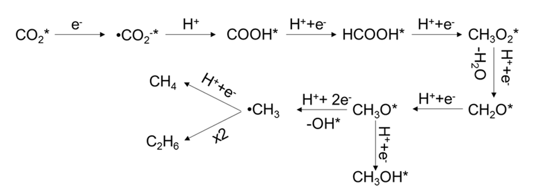
On the basis of the results obtained in the in-situ DRIFTS and EPR spectroscopy studies, the mechanism of alkane (CH4 and C2H6) evolution with SAs Pt-Au/R-TNTs was proposed as Scheme 1. At first, a large amount of the CO2 molecules was adsorbed on the surface of the catalyst and underwent a reaction to produce CO2•− under illumination (path 1), followed by an addition reaction with H to generate COOH* (path 2)50, in which the H was from the photocatalytic H2O splitting. Subsequently, HCOOH*, as an intermediate product, was formed by reduction of the unstable COOH* (path 3). Instead of forming CH2O* from HCOOH* by bond-breaking, CH3O2* should be formed by H addition to the C=O of HCOOH* (path 4), due to the high bonding energy of C-OH. Upon the H accommodation, the C-OH bond of CH3O2* was broken to generate CH2O*(path 5), owing to the lower dehydroxylation energy51. Afterwards, CH3O* was formed by stepwise hydrogenation of CH2O* (path 6) and further formation of CH3OH (path 7) or •CH3 (path 8) was possible in the subsequent hydrogenation steps. Comparing the path of CH3OH generation, the •CH3 formation was predominantly favored by the H3C-O* bond-breaking, which was evident for the strong interaction of the O (H3CO-* bond) with the SAs sites and defects of acidic TiO2 support52-54. At last, CH4 was produced by the reaction of single •CH3 with H (path 9), while coupling of two •CH3 resulted in C2H6 formation (path 10).
CO2* + e- →CO2•−* Path 1
CO2•−* + H+ + e- →COOH* Path 2
COOH* + H+ + e- →HCOOH* Path 3
HCOOH* + H+ + e- →CH3O2* Path 4
CH3O2* + H+ + e- →CH2O* + H2O Path 5
CH2O* + H+ + e- →CH3O* Path 6
CH3O* + H+ + e- →CH3OH* Path 7
CH3O* + H+ + 2e- →•CH3 + OH* Path 8
- CH3 + H+ + e- →CH4 Path 9
- CH3 + •CH3 →C2H6 Path 10
In summary, a state of the art composite catalyst of SAs Pt-Au/R-TNTs, was developed by anchoring of atomic scale Pt and Au on the OVs of self-doped TiO2 nanotubes support. The binary components were dispersed on the surface of the catalyst via strong MSI. The as-prepared SAs Pt-Au/R-TNTs with a composition of 0.33 wt % of SAs metals, performed extremely well on the photocatalytic CO2 reduction, in which the CO2 molecule was initially protonated to form •CH3, and converted further into CH4 and a C-C coupled product of C2H6 with the AQY of 15.2 and 2.7 %, respectively. The efficiency was about 5.5 and 149 times higher than that of the Pt-Au/TNTs and R-TNTs, respectively. The remarkable performance was ascribed to the significant enhancement in separation of photo-generated electron-hole pairs and charge-carrier transmission by the MSI of Pt-O and Au-Ti covalent bonding. Furthermore, the pathway of photocatalytic H2O oxidation changed from •OH generation to O2 evolution upon loading of Pt and Au, resulting in inhibition of the self-oxidization of the photocatalyst. The excellent reproducibility of photocatalytic CO2 reduction was maintained due to an effective controlling of •OH generation, that has also been achieved by the carbonate termination. The present work takes a step forward in the understanding of light-induced charge transfer processes between SAs metals and semiconductor support. New opportunities of binary SACs for constructing high-performance photocatalytic system can be explored based on the results established in the present study.